
Sonic depth finder of the amateur fisher
The electronic key of S1 at the same time opens, and fluctuations of exemplary frequency of 7500 Hz from the G2 generator arrive on the digital PC1 counter. Upon termination of operation of the transmitter the A2 receiver opens and gains normal sensitivity. Ekhosignal reflected from a bottom, is accepted by the BQ1 sensor and after strengthening in the receiver closes S1 key.
Measurement is finished, and indicators of the PC1 counter highlight the measured depth. The next clock impulse transfers again the PC1 counter to a zero condition, and process repeats. the Schematic diagram of the sonic depth finder with a limit of measurement of depth to 59, 9 m is represented by p on fig. 2. Its transmitter represents the duple generator on transistors VT8, VT9 with the T1 transformer adjusted on working frequency.
Necessary for generator self-excitation positive feedback is created by R19C9 and R20C11 chains. ` The generator forms impulses duration of 40 microsec with radio-frequency filling. Operation of the transmitter the modulator consisting of the one-vibrator on transistors VT11, VT12, forming modulating impulse duration of 40 microsec, and the amplifier on the VT10 transistor operates. The modulator works in the waiting mode, starting clock impulses arrive via the C14 condenser. the Receiver of the sonic depth finder is accurate according to the circuit of direct strengthening. Transistors VT1, VT2 strengthen BQ1 accepted by a radiator sensor … ³ ½ ° », the VT3 transistor is used and the peak detector, the VT4 transistor strengthens the pro-detected signal.
On transistors VT5, VT6 the one-vibrator providing constancy of parameters of target impulses and a threshold of sensitivity of the receiver is accurate. From a transmitter impulse the receiver protect the diode limiter (VD1, VD2) and the R1 resistor. In the receiver is applied by p compulsory switching off of the one-vibrator of the receiver by means of the VT7 transistor.
On its base via the VD3 diode the positive clock impulse arrives and charges the C8 condenser. Opening, the VT7 transistor connects base of the VT5 transistor of the one-vibrator of the receiver to a positive wire of a food, preventing thereby possibility of its operation from coming impulses. Upon termination of a clock impulse the C8 condenser is discharged via the R18 resistor, the VT7 transistor is gradually closed, and the one-vibrator of the receiver finds normal sensitivity.
The digital part of the sonic depth finder is collected on DD1-DD4 chips. Its structure includes a key on the element DD1. 1, operated by the RS trigger on the elements DD1. 3, DD1. 4. The impulse of the beginning of the account arrives on the trigger from the transmitter modulator via the VT16 transistor, the terminations - from a receiver exit via the VT15 transistor. the Generator of impulses with exemplary frequency of repetition (7500 Hz) is accurate on the element DD1.
2. The chain of the negative feedback deducing an element on a linear site of the characteristic is made of the R33 resistor and the L1 coil. It creates conditions for self-excitation on the frequency defined by parameters of a contour of L1C18.
Precisely on the set frequency the generator adjust a podstroyechnik of the coil. the Signal of exemplary frequency 🔗 External reference
Related Circuits

Most frequency multiplier circuits utilize an integrated circuit (IC) phase-locked loop (PLL). These circuits typically increase the frequency by an integer factor only. However, this particular circuit is capable of doubling the frequency. Frequency multiplier circuits are essential in various...
The measuring resonant circuit, while actively operating, is loosely coupled to the resonant circuit of the dipper, meaning it is brought close to it. The dipper is tuned from the lowest to the highest frequency. When the dipper and...
The mobile robot is designed to operate in unknown and uncertain environments, featuring autopilot capabilities while avoiding obstacles. It utilizes ultrasonic sensors for range finding due to their simplicity, speed, and cost-effectiveness in information processing. These sensors facilitate functions...
A circuit has been identified that integrates a voltage regulator and filter to isolate the voltage supplied by the receiver for powering an operational amplifier (op-amp) that drives a meter. Additionally, the circuit isolates the carrier frequency from the...
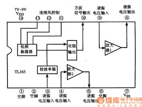
The following circuit illustrates the TL163 integrated circuit used in an ultrasonic remote control circuit diagram. Features include a detector, high-gain amplifier, and low-frequency capabilities. The TL163 integrated circuit serves as a pivotal component in ultrasonic remote control applications, facilitating...
The technology of range finding is extensively employed in civil and industrial fields, such as measurement, medical flaw detection, and car anti-collision systems, due to the relatively lower speed of ultrasonic waves compared to the speed of light. This...