
The H-Bridge
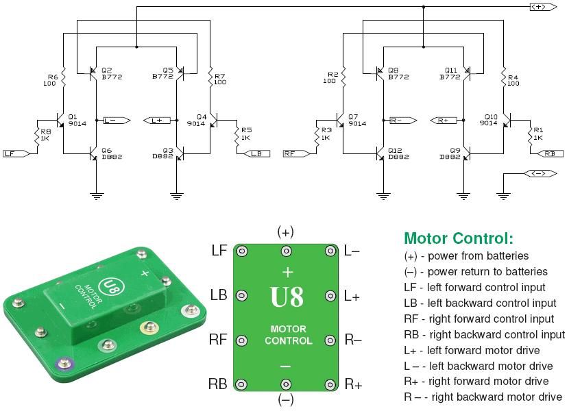
The Snap Circuits Motor Control IC is designed to control the direction and speed of DC motors using an H-bridge configuration. An H-bridge consists of four switches that can be transistors, MOSFETs, or relays, which allow the voltage to be applied across the motor in either direction, thus enabling forward and reverse motion.
In the schematic, the inputs to the H-bridge are typically connected to a microcontroller or a control circuit that generates the necessary signals to switch the transistors on and off. The control signals determine the operation of the motor by adjusting the duty cycle of the PWM (Pulse Width Modulation) signals, which in turn controls the speed of the motor.
The H-bridge may include additional features such as current sensing, thermal protection, and over-voltage protection to ensure safe operation. Often, diodes are included in the design to protect against back EMF generated by the motor when it is turned off or when it changes direction.
The layout of the circuit should ensure that the traces carrying high current are sufficiently wide to handle the load without overheating, and the ground connections should be robust to minimize noise and ensure stable operation. Proper decoupling capacitors may also be placed near the power supply pins to filter out any voltage spikes.
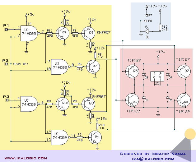
Overall, the Snap Circuits Motor Control IC is a versatile component for educational projects and prototyping, allowing users to easily integrate motor control functionality into their designs.This is the Snap Circuits Motor Control IC, or H-bridge. At the top of the figure you can see the electronic schematic of the Motor Control block. On.. 🔗 External reference
Related Circuits

Learn how to build H-bridges from various online and offline resources. These circuits are not overly complex. Some resources are reliable, while others may not be as helpful. Upon starting to work with H-bridges, it became evident that many...
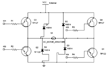
The diagram below illustrates an H-Bridge circuit featuring four inputs and an external power supply. The control application must enable the motor to operate in both forward and reverse directions. The H-Bridge is a crucial component in motor control applications,...
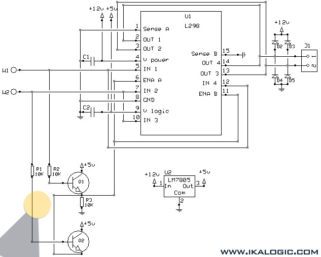
This implementation utilizes the L298 integrated circuit to drive motors and inductive loads with a continuous current capacity of up to 4A. The L298 consists of two independent channels, each capable of driving loads of up to 2A. By...
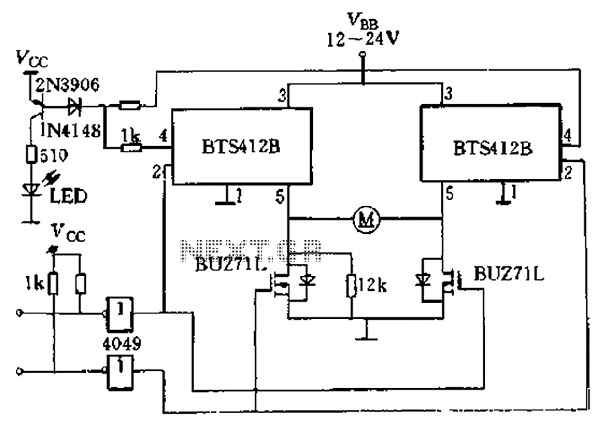
The BTS412B functions as two high-side power MOSFET switches, while two BU271L (50V, Zhang 1n) serve as low-side switches, forming a bi-directional H-bridge DC motor drive circuit. This configuration is designed for electrical automatic door systems, capable of handling...

The 10A H-Bridge Motor Controller circuit appears straightforward, but several critical aspects should not be overlooked. The primary components utilized in the circuit include the TIP147, TIP142, and 2N2222 transistors. The power supply circuit operates at +12V, which is...
A relatively high-power H-bridge motor controller, which is a common method to control DC motors, utilizes inexpensive TIP transistors. A continuous current of 5 Amperes through an H-bridge module may not seem significant to some, depending on their background...