
The light theremin

The theremin operates by detecting changes in capacitance based on the proximity of the player's hands to the sensors, which in this case are facilitated through optical means. The 555 timer chip serves as the core of the circuit, functioning in astable or monostable mode to generate audio signals that can be modified by the inputs from the optical sensors. The circuit design typically includes resistors and capacitors that define the timing characteristics of the 555 timer, thereby influencing the pitch and tone of the sound produced.
In constructing the circuit, attention must be paid to the pin configuration of the 555 timer. The standard 555 timer has eight pins, each serving specific functions, such as triggering, resetting, and outputting the signal. For instance, pin 1 is connected to ground, while pin 8 is connected to the positive voltage supply. The configuration of resistors and capacitors connected to pins 2 (trigger), 3 (output), 6 (threshold), and 7 (discharge) will determine the frequency of the oscillation and, consequently, the sound produced by the theremin.
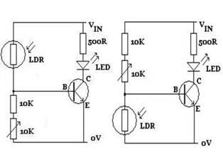
The optical sensors, such as CdS photoresistors, will vary their resistance based on light intensity, allowing for modulation of the sound output as the player's hands move closer or further away from the sensors. By adjusting the values of the resistors and capacitors in the circuit, the user can customize the responsiveness and tonal qualities of the theremin, creating a unique sound experience. Proper soldering and connections are essential to ensure reliable operation and to minimize noise or interference in the audio signal.A "theremin" is an instrument you can play just by changing the proximity of your hands with respect to the instrument`s sensors. Traditional theremins generate the classic spacey, spooky sounds from sci-fi and horror films. Ours is a simple optical version. We`ll use a separate IC chip for this, called a "555 timer chip" (the small black chip on your breadboard). It`s a bit more specialized than the op-amp chip we used for the last build, but they can do similar stuff. This time, try to build the circuit based on the schematic alone. It`s not hard as long as you know the orientation of the 555 timer chip. Looking down from above, there should be a notch or a circle at one end of the chip which corresponds to the notch on the chip in the schematic.
All you need to do is look at each pin on the chip one at a time. Is there a component (resistor, jumper, capacitor, CdS photoresistor, etc. ) connected to it If yes, find that component in your kit. Plug one leg into the 555 pin. Then figure out if the other leg of the component plugs into a different 555 chip pin, or plugs into 9V, or plugs into 0V, etc. 🔗 External reference
Related Circuits

This 6V battery-operated doorbell light circuit can be connected in parallel with any existing AC 230V doorbell. When the doorbell switch is pressed, the bell sounds as usual, and the AC mains supply available across the doorbell is routed...
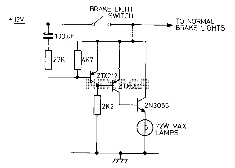
Activating the brake pedal in a vehicle triggers the standard brake lights, followed by a delay before the additional lights are illuminated. A bimetal strip connected in series with the lights can create a flashing effect. The described circuit operates...
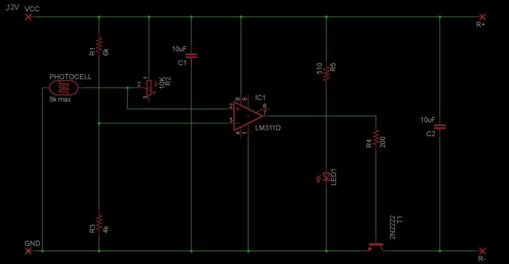
The circuit is designed to sense ambient light levels and activate lights when it is dark. A prototype was successfully built on a breadboard using an LM324 comparator, various resistors, a trimmer resistor, and a photocell. Subsequently, a PCB...
The figures above illustrate the fundamental concept of a robot, which consists of various input and output devices connected to a central processing unit, commonly referred to as the brain. These inputs and outputs are essential for the robot's functionality...
Nowadays, a switch-off delay for vehicle interior lighting is a standard feature. However, certain models with minimal settings or older vehicles leave users in the dark as soon as they enter and close the door. This situation calls for...
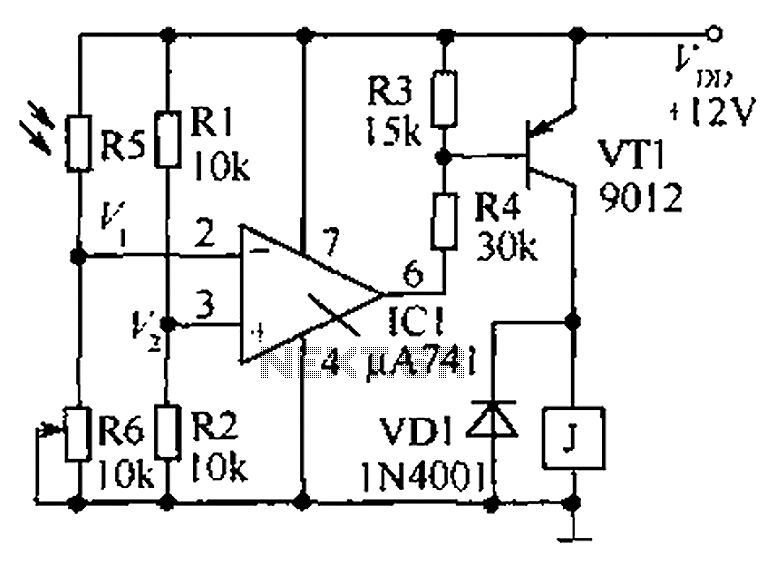
The circuit functions as a precision bright light control circuit, operating independently of variations in power supply voltage and ambient temperature. Resistors R1, R2, R6, and the photosensitive resistor R5 form a two-arm Wheatstone bridge. The precision bright light control...