
The One-shot Monostable Multivibrator Circuit

The monostable multivibrator is a crucial component in electronic circuits, functioning as a pulse generator that produces a single output pulse in response to a triggering input. This circuit is characterized by its ability to return to a stable state after a temporary output pulse, hence the term "monostable."
The typical configuration of a monostable multivibrator involves a timing resistor (R) and a timing capacitor (C) connected to a trigger input. When the circuit is triggered, the capacitor charges through the resistor, and the output pulse width is determined by the RC time constant, calculated using the formula \( T = 1.1 \times R \times C \), where \( T \) is the duration of the output pulse in seconds.
Commonly, the 555 timer IC is utilized to construct monostable multivibrators due to its versatility and ease of use. In this configuration, the trigger input is connected to pin 2 of the 555 timer, while the timing components are connected between pin 6 (threshold) and pin 3 (output). The output pulse can be used in various applications, such as debounce circuits, timers, and pulse width modulation.
In practical applications, the monostable multivibrator can be employed to generate precise timing intervals for various electronic devices, ensuring accurate signal processing and control. Its simplicity and reliability make it an essential tool for engineers and hobbyists in the field of electronics.Electronics Tutorial about the Monostable Multivibrator Circuit also known as a One-shot Monostable Multivibrator used as a Pulse Generator Circuit.. 🔗 External reference
Related Circuits
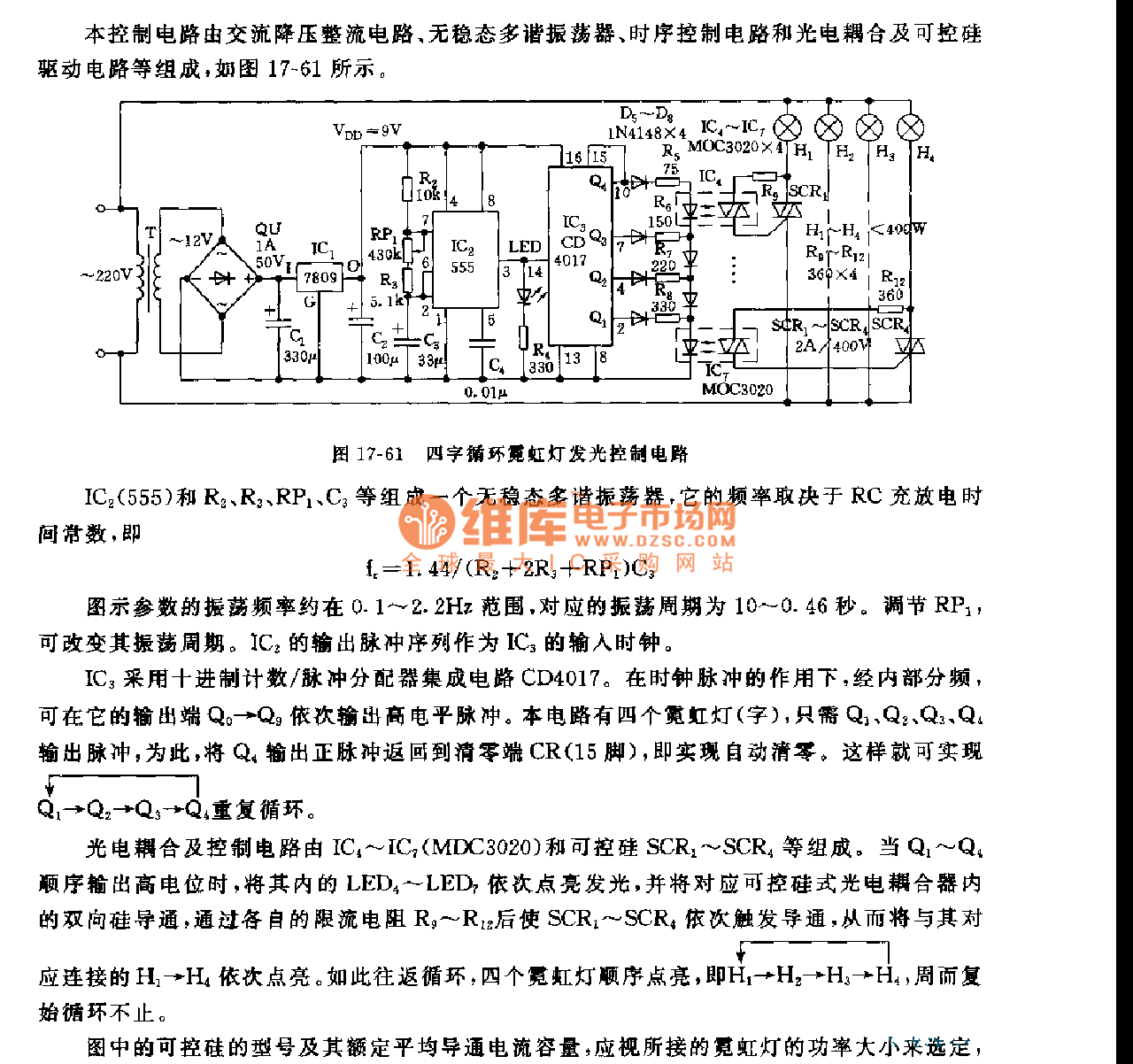
This control circuit consists of an AC step-down rectifier circuit, an astable multivibrator, a timing control circuit, an optocoupler circuit, and an SCR driving circuit, as illustrated in Figure 17-61. The astable multivibrator is formed using IC2 (555), resistors...
A newer version of this circuit board is available. Rev 4 includes a faster CPU, more memory, more I/O, and an optional LCD. It is recommended to use Rev 4 for new projects. Although the older board is no...
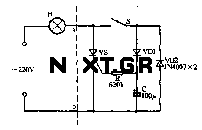
Closing the switch S allows the AC positive half-cycle to flow through diode VDI and resistor R, causing the SCR to open simultaneously at both ends of the capacitor C, which becomes fully charged. During this phase, the positive...
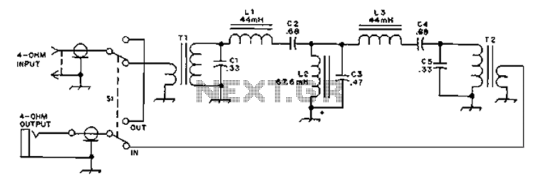
The circuit provides an 8-ohm output for connecting communication receivers and low-impedance speakers or headphones, featuring harmful interference suppression for continuous random voice transmission. The passband ranges from 55 to 2530 Hz with a 3 dB bandwidth. Inductors L1...
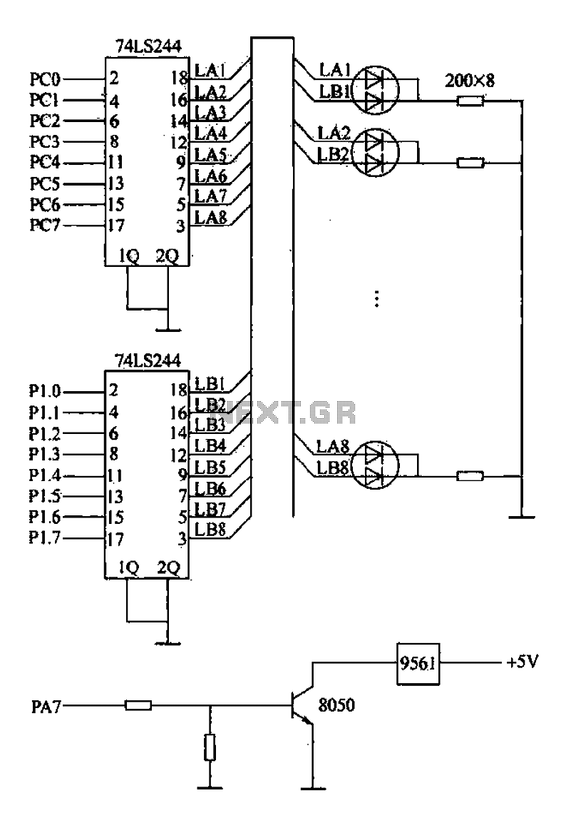
Alarm interface circuitry featuring a two-color light-emitting diode (LED) display. When LAi is at a high level and LBi is low, the green LED lights up; conversely, if LAi is low and LBi is high, the red LED lights...
Cuckoo Sound Generator Circuit Schematic. This circuit generates a two-tone effect similar to the cuckoo song. It can be utilized for doorbells or other applications due to a built-in audio amplifier and loudspeaker. The Cuckoo Sound Generator Circuit is designed...