
The Original 2 Phone Link=
When phone #1 picks up its handset, a DC loop is formed between the handset, the 1k winding of Tx1, the 0V earth terminal, the +12 volts terminal, and the LEDs inside OC1 and OC3. IC1, an NE556 dual timer chip, is continuously active, pulsing on and off at output pin 9, which drives the second half of the timer chip via D1 to pin 4, generating ring pulses and a ringing tone from pin 5 through capacitors C3 and C4 to the 8-ohm windings of Tx1 and Tx2. The transistor within OC1 switches on hard, pulling its collector lead low, allowing ring pulses from pin 9 of IC1 to flow through R5 and Q1 to the emitter of OC1, then to its collector lead, which connects to the negative lead of buzzer B2, thus signaling the other phone.
When the second phone is picked up, OC2 and OC4 also form a DC loop with the 1k winding of Tx2 and the LEDs within the optocouplers. The transistors in OC1 and OC2 create a link to the +12 volts supply near phone #1, routed through diode D2 to the junction of pins 12 and 8 of IC1. This effectively stops the ringing, halting both ring pulses from pin 9 and the ringing tone from pin 5 for the duration of the call. Once both phones are returned to the on-hook position, all four optocouplers (OC1 to OC4) deactivate, allowing IC1 to resume pulsing and providing the ringing tone. However, neither of these outputs will affect the handsets until one is picked up again to initiate the next call.
The transmission bridge consists of Tx1 and OC3, along with Tx2 and OC4, as well as capacitors C5 and C6. The 1k windings serve to prevent speech signals (AC signals) from being grounded through the earth connection. The capacitors facilitate the passage of these signals between handsets while blocking any DC voltages that could cause interference. This circuit represents a simplified version of the Stone Transmission Bridge, which is well-suited for its intended purpose.This is the circuit that sparked off all the other Link Telephone Intercom designs. Originally designed back in 1996 with heavy duty relays and their contact banks, it was updated late last year with the addition of IC1 in place of a simpler transistor multivibrator, the replacement of all relays and contact banks with optocouplers, and the additi on of the two transformers as part of the transmission bridge (see explanation below) which was comprised partly of the relay coils. If you just want simple ‘no frills ’ communication from one phone to another, then this is the right circuit for you!
This version is much more compact, more economic on power drain (yes, you can run it off of batteries – eg: a 12 volt Gel Cell!) and has no moving parts, except for the switch hooks inside each of the phone handsets. This was one of the earliest Link designs. It works by either caller simply picking up their handset and ‘buzzing ’ the other phone. There are no numbers to dial (in fact, no dial tone either – just ring tone, which pulses on and off in unison with the buzzer at either end when a call is in progress.
) Let ’s assume that #1 picks up their handset. This forms a DC loop between the handset, the 1k winding of Tx1, the 0v_ earth terminal, the +12 volts terminal and the leds inside OC1 and OC3. IC1 (an NE556 dual timer chip) is always ‘on ’ –that is, it ’s always pulsing on and off at output pin 9, which then drives the second half of the timer chip on and off via D1 to pin 4, producing ring pulses, and ring tone from pin 5 via C3 and C4 to the 8R windings of Tx1 and Tx2.
The transistor inside OC1 switches on hard, taking its collector lead low, and ring pulses are fed from pin 9 of IC1 via R5 and Q1, to the emitter of OC1, through to its collector lead, and then on to the –ve lead of buzzer B2, thus ‘buzzing ’ the other phone. When that phone is picked up off hook, OC2 and OC4 also form a DC loop along with the 1k winding of Tx2 and the leds inside the optocouplers.
The transistors inside OC1 and OC2 now form a ‘link ’ (no pun intended) from the +12 volts supply (shown at left near phone #1) through to the junction of pins 12 and 8 of IC1, via diode D2. This effectively halts the ringer, and both ring pulses from pin 9 and ring tone from pin 5 cease for the duration of the call.
When both phones are hung up back to the on hook position, all four optocouplers (OC1 to OC4) are switched off. IC1 will now resume pulsing and providing ring tone, but neither one of these outputs will have any effect on either phone handset, until one or the other is picked up off hook again, to make the next call.
The ‘transmission bridge ’ mentioned earlier, comprises of Tx1 and OC3 along with Tx2 and OC4, as well as C5 and C6. Basically, the 1k windings prevent speech signals (which are an AC signal) from being grounded through the earth connection.
The two capacitors allow these signals to pass between the handsets, but block any DC voltages from interfering with them. This circuit is known as a Stone Transmission Bridge ” and although I have employed a simplified version of it, it ’s quite suitable for our purposes.
Happy chatting on the line … ©Austin Hellier 1996 - 2003. 🔗 External reference
Related Circuits
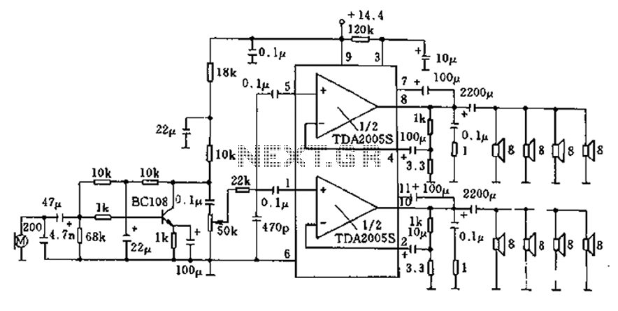
20W bus radio and megaphone circuit utilizing the TDA2005S double low-frequency power amplifier integrated circuit design. The front end can be connected to either a microphone input or a low-frequency radio output voltage amplification stage. Each TDA2005S provides 10W...
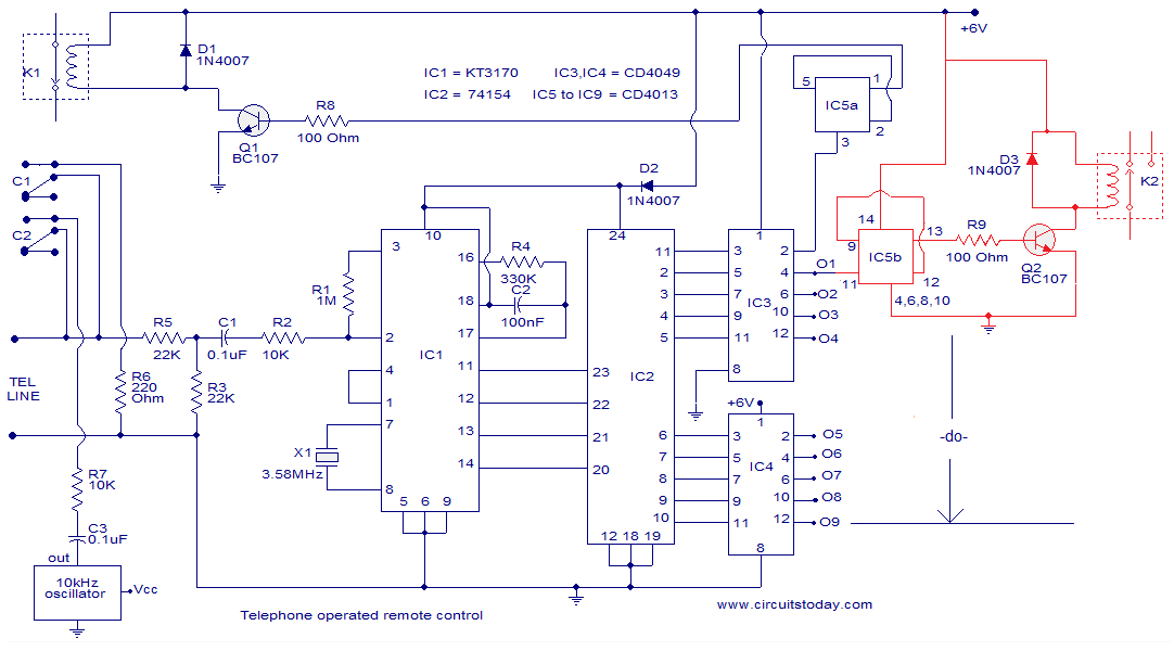
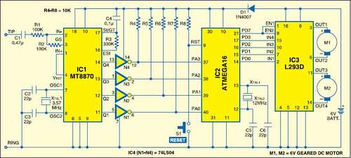
The circuit described is a telephone-operated DTMF remote control that can switch up to nine devices using the telephone keys 0 to 9. The digit 0 is utilized to toggle the telephone system between remote switching mode and normal...
This article discusses several opamp-based headphone amplifier circuits, including suggestions for selecting opamps, input coupling and filtering, high current output stages and power supply options. There are no recommendations for specific opamp brands or models. For tube devotees, there...
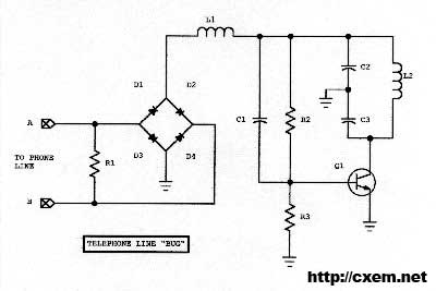
Wireless Telephone Bug. This project enables monitoring of a phone line as soon as the phone is off-hook. A regular FM broadcast band radio can be utilized for this purpose. The Wireless Telephone Bug is a circuit designed to allow...
The following circuit illustrates the A933 Transistor Telephone Listening Circuit Diagram. Features include the ability to tune from 88 to approximately 94 MHz and a simple design. The A933 Transistor Telephone Listening Circuit is designed to function as a radio...
This instructable is categorized under 13 - 18 in the National Robotics Week Robot Contest. The National Robotics Week Robot Contest encourages innovation and creativity in robotics among participants aged 13 to 18. This category represents a significant opportunity for...
Warning: include(partials/cookie-banner.php): Failed to open stream: Permission denied in /var/www/html/nextgr/view-circuit.php on line 713
Warning: include(): Failed opening 'partials/cookie-banner.php' for inclusion (include_path='.:/usr/share/php') in /var/www/html/nextgr/view-circuit.php on line 713