
The Remote Controlling Circuit
The project utilizes a sophisticated integration of sensors and feedback mechanisms to enhance the operator's interaction with the robot. The virtual reality helmet serves as a primary interface, providing high-resolution visual feedback that allows for precise control and situational awareness. The audio system, with its surround sound capability, complements the visual feedback by immersing the operator in the environment, enhancing the realism of the experience.
The tactile feedback system is particularly noteworthy. The jammers provide a physical sensation of grip, simulating the experience of holding objects. This feedback is critical for tasks requiring delicate manipulation, as it allows the operator to adjust their actions based on real-time feedback. The vibration feature adds another layer of realism, alerting the operator to contact with objects, which is essential for effective remote operation.
The fail-safe system is a crucial aspect of the design, ensuring that the robot can continue to function even if some sensors fail. This redundancy is vital for safety, as it guarantees that the operator is not subjected to harmful forces. The computer's programming includes safeguards that prevent dangerous actions, enhancing the overall reliability of the system.
The ADC's role in converting analog signals from the potentiometers into digital signals is central to the operation of the circuit. The eight output pins of the ADC allow for a wide range of data representation, enabling detailed control over the robot's actions. The integration of analog and digital signals facilitates seamless communication between the operator and the robot, ensuring that commands are executed accurately.
In summary, this project exemplifies the convergence of advanced sensor technology, feedback systems, and digital signal processing, resulting in a highly interactive and responsive robotic control system. The careful design considerations, including fail-safes and immersive feedback mechanisms, contribute to its effectiveness and user safety.The design of this project depends on the sensors. The control module and the robot both contain sensors. The computer, in turn, analyzes the signals to make the appropriate output actions. As previously mentioned, the potentiometers are the sensors on the control unit. They send the signal to the computer that interprets the data. However, the co ntrol module also has features to receive signals from the computer, which gives the controller a feel of the reality that the robot is in. This feature is comprised of three different devices. The first is a virtual reality helmet, with 32-bit colour, and approximately 500, 000 pixels per eye.
This gives the operator a real sense of the reality, and allows him to operate the device effectively. A second less important feature is sound, this helps the operator gain more of a three dimensional feeling of the area.
The third feature is touch. Special jammers ” operate when the robot reports that it has grabbed onto something. The jammers ” are essentially motors that reverse, therefore jamming the joint from further bending. Also, another way to send force-feedback is through vibration. Very much like the vibrate signal on a cell phone, the tip of the fingers on the suit vibrates when the robot touches something. As well, the temperature inside the suit is regulated, to a smaller degree of course, to reflect the temperature that the robot is experiencing.
There are three corresponding sensors on the robot. The first is visual. It consists of two cameras on the robot, through which visual data is transmitted to the computer, analyzed, and then sent to the suit. The seco nd is the audio. This is achieved through special microphones on the robot. The audio signals are processed by the computer, and sent out to 8 speakers laid around the operator`s room for special surround sound effect.
The pressure sensors, or touch sensors, are essentially a different type of potentiometer. The resistance decreases when the applied pressure becomes greater. It gives the operator a feel of how tight the grip is on a specific object. There are also additional probes that detect the temperature and other environmental changes such as humidity. All of the above has to be built with a fail-safe system. The fail-safe system does two things. First, a second or even third set of sensors on the robot allows it to still function, even after the original set of sensors have been knocked out.
Secondly, a fail-safe in the computer program makes sure that if the robot is somehow crushed, for example, the computer does not apply the same crushing pressure on the operator, and thereby makes sure he doesn`t get killed. This circuit demonstrates the function of the ADC (Analog – Digital Converter). The resulting output on this circuit is a feed to a computer and an 8-bit LED display. The 8 LEDs each represent 1 binary digit. The total maximum number of different outputs with the 8-bit LED is previously described to be 256 different outputs.
The current circuit hooks up to the computer with 8 bit output, and the hand movement is displayed on the computer screen. This is where the functions of the remote and potentiometer circuits we built above are combined. The circuit is designed to incorporate analogue and digital signals. The ADC chip converts analogue signals into 8 bit digital signals. Signals are either on or off (1 or 0). The signal from the potentiometer is fed to the ADC chip. The ADC outputs signals in eight different pins. This signal is inputted into the computer for analysis so that the appropriate functions are completed.
The resistance level to the computer ranges from 0 – 255. Therefore, depending upon the signal that goes into the computer through the 8 bit number generated by the chip, certain actions (in this case, computer graphics of a hand) are done. The parallel port can only take 5 inputs, yet there are 8 bits of information. Therefore 🔗 External reference
Related Circuits
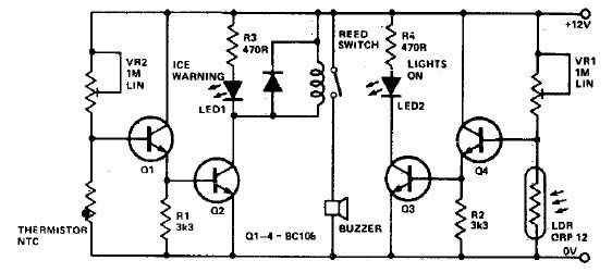
This electronic project circuit diagram for an ice warning and lights reminder system alerts drivers when their vehicle lights should be activated and warns them if the outside temperature approaches zero degrees Celsius. The system employs an LED indicator...
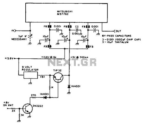
Using a Mitsubishi M57762 amplifier module, this amplifier delivers 20 W output at 1296 MHz. A single 12 V nominal power supply can be used. The Mitsubishi M57762 is a high-performance RF amplifier designed for applications requiring significant power output...
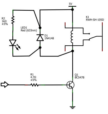
The BC547B transistor has a collector-base voltage (Vcbo) of 50V, a collector-emitter voltage (Vceo) of 45V, and an emitter-base voltage (Vebo) of 6V. In contrast, the BC548 transistor in the original circuit has a Vcbo of 30V, a Vceo...
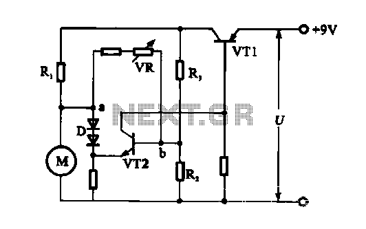
The electronic circuit for steady speed motor applications utilizes an automatic remote control system to regulate the motor power supply, thereby achieving consistent speed control. The circuit diagram illustrates a DC motor connected to the system. Given that the...

The LTC4000 high voltage controller, developed by Linear Technology, can be utilized to create a straightforward high current LiFePO4 battery charger. This charger delivers a fixed output voltage of 12 volts with a maximum output current of 15 A....
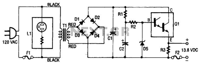
This regulated power supply consists of a step-down transformer T1, a full-wave rectifier bridge (D1 through D4), and a filtering regulator circuit made up of C1, C2, R1, R2, R8, D5, and Q1. When 120 Vac is provided, the...
Warning: include(partials/cookie-banner.php): Failed to open stream: Permission denied in /var/www/html/nextgr/view-circuit.php on line 713
Warning: include(): Failed opening 'partials/cookie-banner.php' for inclusion (include_path='.:/usr/share/php') in /var/www/html/nextgr/view-circuit.php on line 713