
The SC (Schmitt Comparator) Head

The provided description indicates a project involving a circuit that utilizes flashing LEDs to signal a "lock" status. This type of design typically involves a microcontroller or a logic circuit that manages the state of the LEDs based on specific input conditions, such as a switch or sensor indicating a locked or unlocked state.
In a basic schematic, the circuit may consist of the following components:
1. **Microcontroller**: This component acts as the brain of the circuit, processing inputs and controlling outputs. It can be programmed to change the state of the LEDs based on user interaction.
2. **LEDs**: Light Emitting Diodes are used to visually indicate the lock status. Two LEDs could be implemented: one for "locked" (perhaps flashing) and another for "unlocked" (steady light).
3. **Resistors**: Current-limiting resistors are necessary to prevent excessive current from damaging the LEDs. The resistor values can be calculated based on the forward voltage and current specifications of the LEDs.
4. **Power Supply**: A suitable power source, such as a battery or a DC power adapter, will be required to power the circuit. Voltage regulators may be needed if the microcontroller requires a different voltage than the LEDs.
5. **Input Switch or Sensor**: A physical switch or a sensor can be used to detect the lock state. When activated, it sends a signal to the microcontroller to change the state of the LEDs.
6. **Transistors (optional)**: If higher current is needed for the LEDs or if the microcontroller's output pins cannot handle the load, transistors can be used to drive the LEDs.
The flashing behavior of the LEDs can be programmed using a simple loop in the microcontroller's firmware, where the LEDs are turned on and off at specific intervals to create the flashing effect. The timing can be adjusted to suit the desired visual cue for the user.
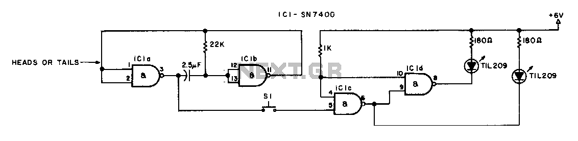
Overall, this circuit design effectively communicates the lock status through visual indicators, enhancing user experience and safety.I`ll eventually post an explanation, but in the meantime, here it is. Meanwhile, a slightly refined version (with flashing LEDs to indicate "lock") was posted a few weeks later: 🔗 External reference
Related Circuits
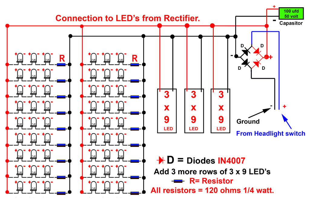
Gently bend the leads of the LEDs and, using the provided schematic circuit diagram, begin to solder. Once soldering is complete, it should... To successfully assemble the LED circuit, it is essential to follow a systematic approach. Start by preparing...
The switch must be a push-to-make, release-to-break type. An effective circuit utilizing a push-to-make, release-to-break switch can be designed for various applications, particularly in control systems where momentary activation is required. This type of switch, often referred to as a...

The A2045 utilizes the same circuit as the A2052. Unlike the larger A2052 board, which is mounted with three snap-top standoffs, the more compact A2045 is attached by gluing it onto a rectangular flange that fits around the underside...
This device is a simple timer that keeps the headlights of a vehicle illuminated for approximately 1 minute and 30 seconds. This feature is particularly useful when accessing dark areas, eliminating the need to return to manually switch off...
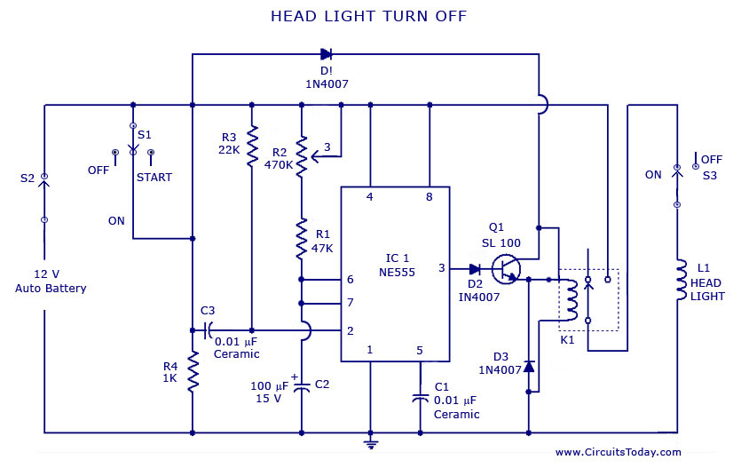
A circuit that can automatically turn off the headlights or lamps of a vehicle after a preset time. This light switching circuit is constructed using a 555 timer integrated circuit (IC). The described circuit utilizes the 555 timer IC in...
Grounding the blue wire at the headlamp switch causes the lights to illuminate, indicating a faulty switch. Continuity of the switch has already been verified. The relay consists of two small terminals and two larger ones. The smaller terminal,...