
H Bridge Direct Current Motor Control Circuits
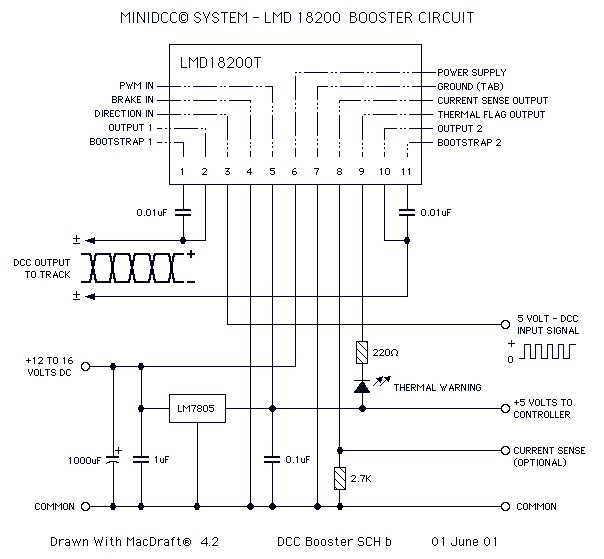
The H-Bridge circuit is a critical component in controlling the direction and speed of DC motors, particularly in applications such as model railroads where precise control is essential. In this schematic, the LMD 18200, a CMOS H-Bridge driver, is utilized, capable of delivering up to 3 Amps of continuous current. This allows for the effective operation of small to medium-sized DC motors, providing the necessary torque and speed control.
The design incorporates a 5V voltage regulator, which is essential for powering the DCC signal generation and display circuitry. This regulator ensures that the control logic operates reliably, as the DCC system requires a stable voltage for proper signal transmission and reception. The integration of the MiniDCC© system indicates that this circuit is tailored for hobbyists looking to implement a DIY DCC solution, enhancing the functionality of model trains through digital control.
The H-Bridge configuration allows for bidirectional control of the motor. By switching the polarity of the voltage applied to the motor terminals, the direction can be reversed. Additionally, PWM (Pulse Width Modulation) control can be employed to adjust the speed of the motor, providing a versatile solution for various operational needs in model railroading.
Overall, this H-Bridge circuit design serves as a robust foundation for those interested in developing their own DCC boosters or PWM motor controllers, leveraging both CMOS technology for efficiency and ease of use in hobbyist applications.This page features H-Bridge circuits used for controlling direct current motors. Several designs are shown using both CMOS and Bi-Polar power devices. These circuits could be used as the basis for Model Railroad DCC Boosters or PWM motor controllers. The first schematic is for a basic 3 Amp - DCC Booster using the LMD 18200 CMOS, H-Bridge. Included in the design is a 5Volt regulator that supplies power to the DCC signal generation and display circuitry. This circuit was designed be used with the MiniDCC© system. - A DCC ( Digital Command Control) do-it-yourself project... 🔗 External reference
Related Circuits
This circuit is designed around a 555 timer and utilizes a minimal number of components. Due to its simplicity, it can be easily constructed and operated by beginners. The circuit leverages the 555 timer IC, which is a versatile and...
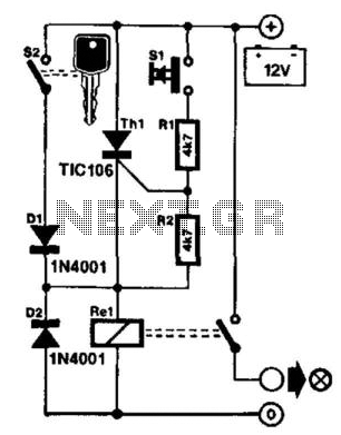
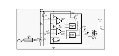
It is frustrating to discover that the car headlights have been left on, resulting in a dead battery. One solution to this problem is the proposed control circuit. This circuit does not issue a warning; instead, it takes action:...
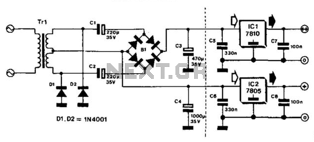
This bridge circuit is designed for applications requiring two unequal supply voltages. The lower voltage is obtained using a transformer with symmetric windings and half-wave rectification of the potential across one winding. The higher voltage is derived from the...
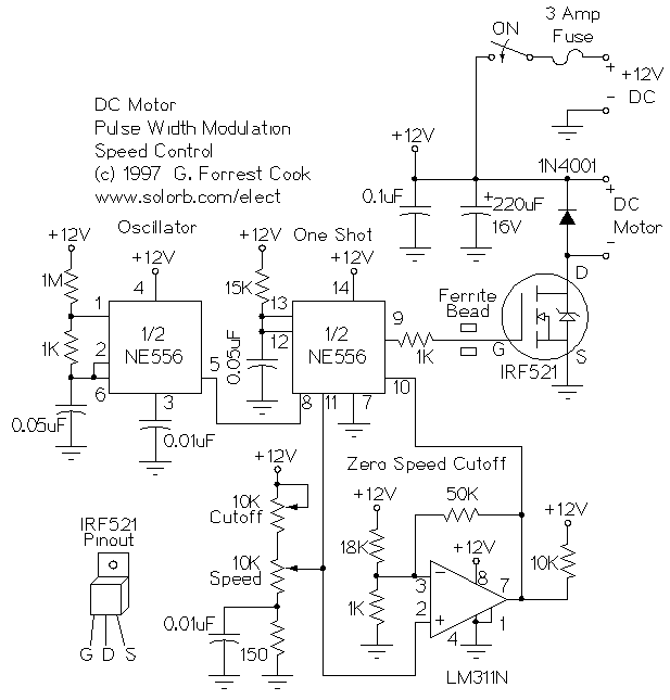
This is a circuit for controlling the speed of small DC motors; it works nicely as a speed controller for an HO or N gauge model railroad. More: The left half of the 556 dual timer IC is used...
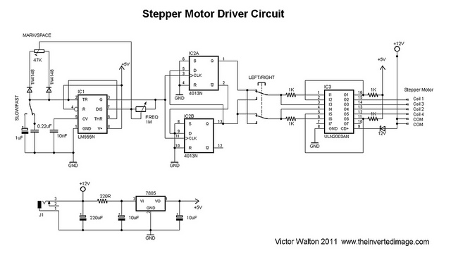
The commonly used 555 timer is configured for a variable mark/space ratio, which is essential for this application. Additionally, two D-type flip-flops (4013) are employed to provide the necessary count for the ULN2003 stepper motor driver. ULN2003 components may...
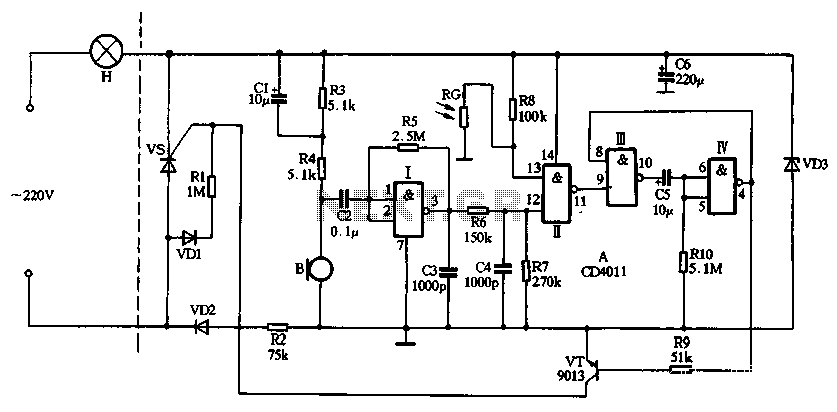
The circuit utilizes CD4011 digital circuits to create a sound-activated light lamp with a dual-control delay section. The left portion of the circuit represents the lighting lines, while the right part consists of the sound and light control delay...