
Thermometer meter slinger 2
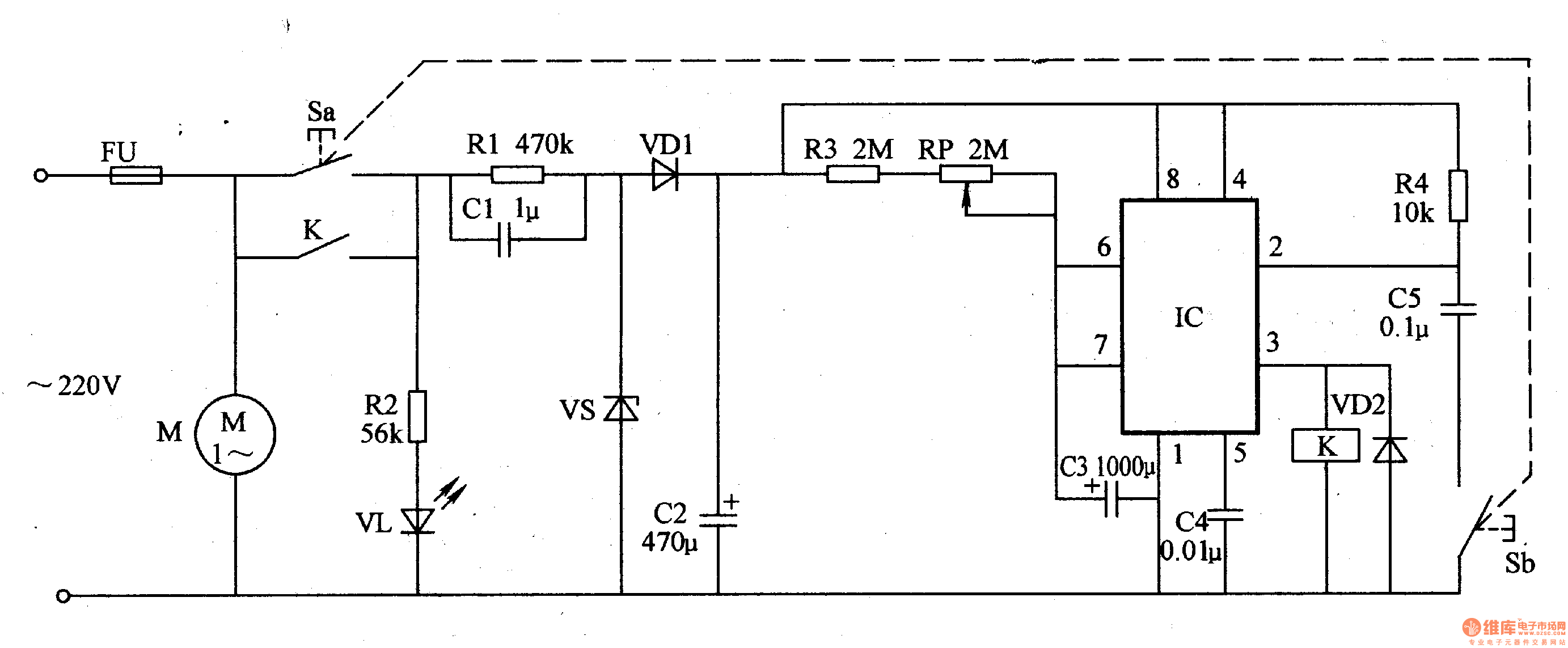
The thermometer meter slinger circuit is designed to provide precise temperature measurements while allowing for adjustable timing control of the meter slinger mechanism. The power supply circuit is essential for converting AC voltage to a usable DC voltage, ensuring that all components receive the necessary power for operation. The fuse (FU) is a protective element that prevents overcurrent conditions, while the power supply buttons (S) allow users to turn the circuit on or off. Resistors (R1, R2) and capacitors (C1, C2) are used to filter and stabilize the power supply output, with the LED (VL) providing visual indication of power status.
The timing control aspect of the circuit is crucial for the operation of the meter slinger. Resistors (R3, R4) and the potentiometer (RP) work together to set the time constant for the charging of capacitor C3. By adjusting the potentiometer, the user can change the resistance in the timing circuit, thereby altering the charge time of C3. This adjustment directly influences the duration for which the relay (K) is activated, controlling the operation of the motor (M). The relay acts as a switch that can handle higher currents, allowing it to turn the motor on or off based on the timing established by the capacitor's charge.
Capacitors C4 and C5 may also be employed for additional timing or filtering purposes, ensuring stable operation under varying conditions. Diode VD2 serves to protect the circuit from voltage spikes that may occur when the relay coil is de-energized, safeguarding sensitive components. Overall, the design of the thermometer meter slinger circuit integrates both power management and timing control, enabling efficient and accurate temperature measurement applications.The thermometer meter slinger circuit is composed of power supply circuit and meter slinger timing control circuit, it is shown in the figure 9-135. The power supply circuit is made of fuse FU, power supply button S(Sa, Sb), resistors R1, R2, capacitors C1, C2, power supply indication LED VL, steady voltage diode VS and rectifier diodes VD1.
The m eter slinger timing control circuit consists of resistors R3, R4, potentiometer RP, capacitors C3-C5, relay K and diode VD2. C3`s charge time can be changed by adjusting RP, then it can control M`s run time. 🔗 External reference
Related Circuits
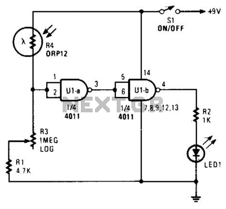
Two gates of a 4011 IC are utilized as a comparator. When the resistance of R4 decreases, the voltage at pins 1 and 2 increases, resulting in a logic zero at pin 3. This causes pin 4 to go...
The Inter-Power SWR-5 upper right isn't worth a penny. Got it from a mate to use with a beacon, but I burnt it out with only 3.5-4W morse signal on 70cm. Removed the bridge and installed my own pick-up...
This is a simple 3-digit digital voltmeter. A PIC16F676 microcontroller is utilized to read analog signals (voltage) and display the value on a 3-digit 7-segment display. Similar principles can be applied to measure DC current using a parallel resistor...
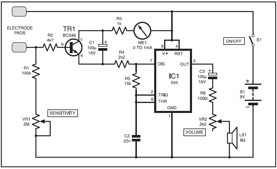
This instrument is designed to help relieve nervous tension for individuals returning home from work with lingering stress. Known as the Galvanic Skin Response Monitor, it operates based on changes in skin resistance that correlate with emotional states. Increased...
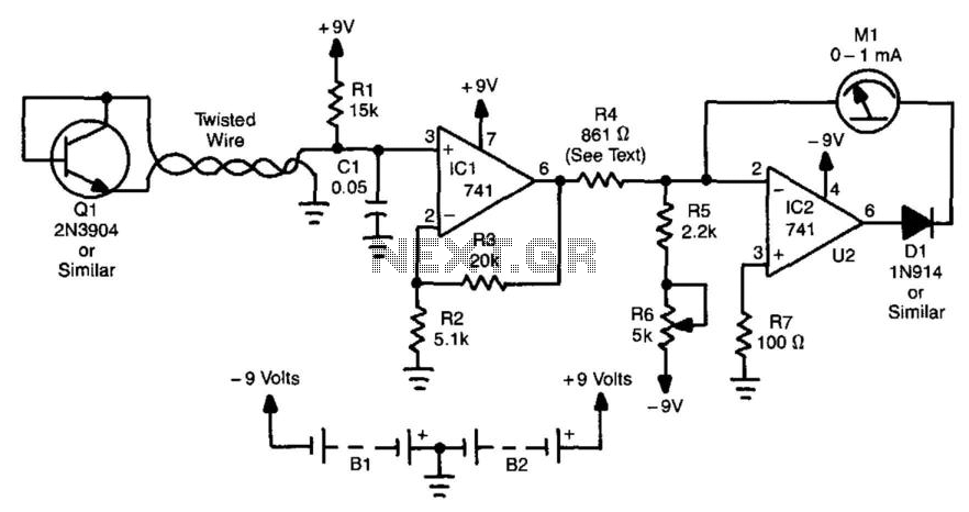
This thermometer is capable of measuring temperatures from -30 to +120 °F. A diode-connected 2N3904 transistor forms a voltage divider with R1. The transistor serves as the temperature sensor and should be connected to the rest of the circuit...
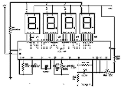
The circuit presented is a highly effective and precise digital voltmeter with an LED display utilizing the ICL7107 from Intersil. The ICL7107 is a high-performance, low-power, 3.5-digit analog-to-digital converter (ADC). This integrated circuit (IC) incorporates internal components such as...