
Thyristor Tester
The presented circuit is designed to facilitate the rapid assessment of thyristor devices, specifically Silicon Controlled Rectifiers (SCRs) and triacs. The functionality of the circuit allows for comprehensive testing across all four quadrants of triac operation, which is essential for understanding the behavior of these devices under different electrical conditions.
The schematic typically includes a power supply, a control mechanism (such as a microcontroller or manual switch), and various test points connected to the thyristor being evaluated. The power supply provides the necessary voltage and current levels required for testing, while the control mechanism enables the user to switch between different testing modes.
For SCR testing, the circuit may employ a gate trigger circuit to initiate the conduction state of the SCR. This is crucial for determining the gate sensitivity and the holding current of the device. For triac testing, the circuit should be capable of applying voltage in both polarities and at various phase angles to verify the device's performance in all four quadrants.
In addition, the circuit may feature indicators such as LEDs or a digital display to provide real-time feedback on the operational status of the thyristor being tested. This immediate visual confirmation aids in diagnosing faults or verifying the functionality of the device.
Overall, this thyristor testing circuit is an essential tool for engineers and technicians working with power electronics, ensuring that thyristors are functioning correctly before being integrated into larger circuits or systems.The circuit in the diagram is a very handy tool for rapidly checking all kinds of thyristor (SCR, triac, ). In case of a triac, all four quadrants are te.. 🔗 External reference
Related Circuits
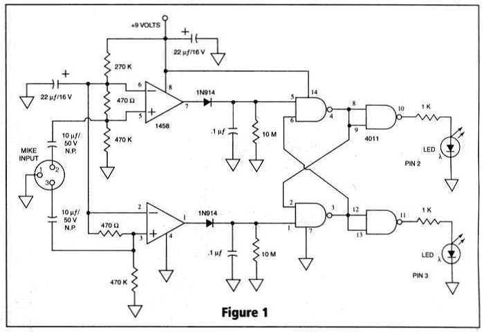
Many things can go wrong in a modern recording studio, but few are as difficult to track down as reversed microphone polarity. When a microphone is placed in front of a sound source, a positive pressure on its diaphragm...
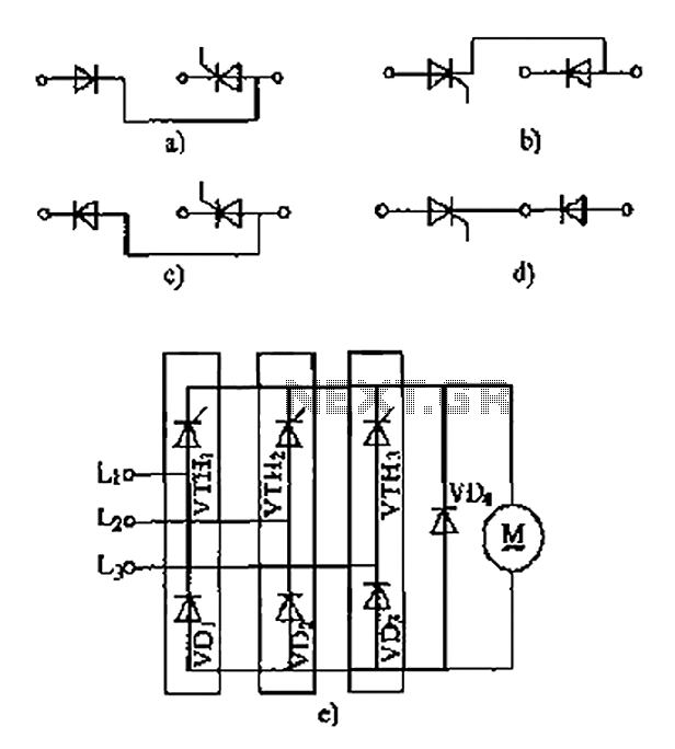
The thyristor linking arm rectifier module is a three-phase half-controlled bridge rectifier circuit. The thyristor-rectifier module linking arm consists of a thyristor and a rectifier diode connected in series or parallel, designed to fulfill specific requirements in power circuits....
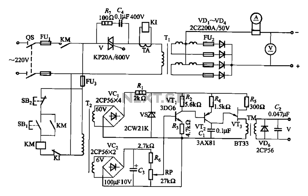
A 500A-6V single-phase power supply circuit designed for thyristor electroplating. This circuit can output a continuous DC current of 500A at 6V, which is adjustable for plating processes. It incorporates a single-junction transistor as part of the trigger circuit,...
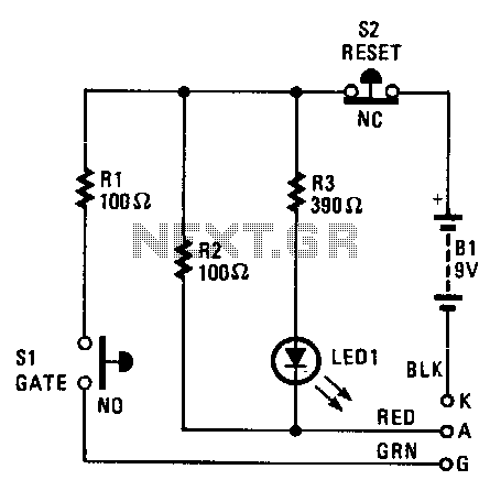
The cathode, anode, and gate of the Device Under Test (DUT) are connected to the unit's K, A, and G terminals, respectively. Pressing switch S1 supplies a gate current to the DUT, triggering it to turn on. Resistor R1...
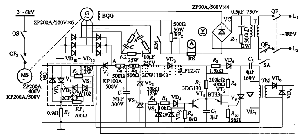
The circuit depicted in Figure 16-105 illustrates a synchronous motor. The components include BQ, which represents its field winding, and G, which denotes the AC excitation for the motor. The notation BQG indicates the field winding, with an empty...
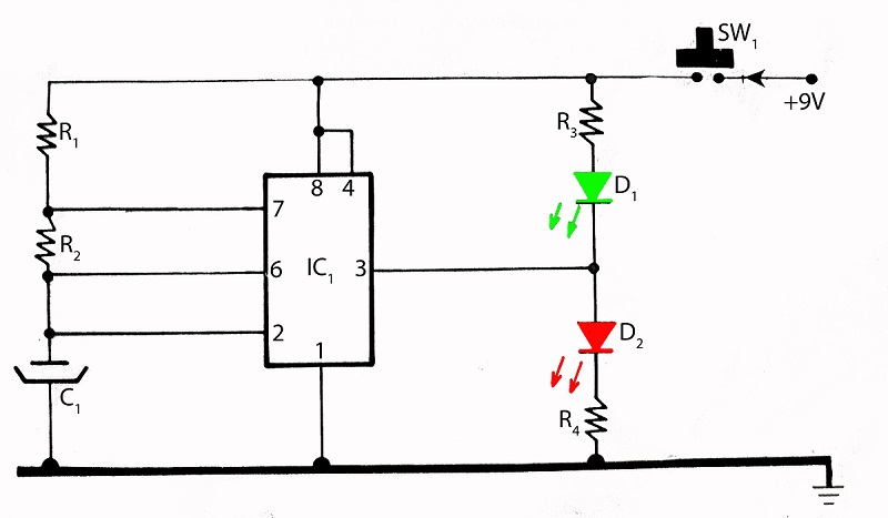
The integrated circuit (IC) tester featured on this website is specifically designed for the LM555 timer IC. This circuit is utilized for testing the functionality of the timer IC, and it includes a circuit diagram along with techniques for...