
Tilt Alarm Circuit
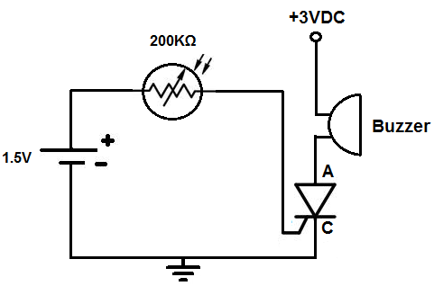
This alarm activation circuit utilizes a tilt sensor to detect the orientation of the device. The tilt sensor typically comprises a conductive ball that rolls within a housing. In its upright position, the ball makes contact with a conductive plate, completing a circuit that allows current to flow through the sensor to ground. This low resistance path ensures that most of the current bypasses the gate of the SCR, keeping it in an off state. The SCR is positioned to control the buzzer, which serves as the alarm output.
The SCR is a three-terminal device with an anode, cathode, and gate. When the tilt sensor is upright, the SCR remains inactive because the gate does not receive sufficient voltage due to the majority of current flowing through the sensor to ground. However, once the tilt sensor is activated by tilting the device, the ball moves away from the conductive plate, effectively opening the circuit. In this state, the resistance of the tilt sensor increases significantly, redirecting the current to the gate of the SCR. This triggers the SCR, allowing current to flow from the anode to the cathode and energizing the buzzer connected to the anode.
The circuit operates on a 9V DC supply, which is connected in parallel to the tilt sensor and the resistor. The 10K resistor is crucial as it forms a voltage divider with the tilt sensor, ensuring that the SCR gate receives the appropriate voltage when the tilt sensor is inactive. The design allows for customization where the buzzer can be replaced with other alerting mechanisms, depending on the application requirements. This flexibility makes the circuit suitable for various scenarios, including security systems and equipment monitoring, where tilt detection is essential.
In summary, this tilt-activated alarm circuit exemplifies an effective application of a tilt sensor and SCR in providing a reliable alert mechanism for devices that may be at risk of tipping over. The design's simplicity and adaptability make it an excellent choice for enhancing the safety and security of electronic devices.This is a circuit where an alarm will go off once the circuit is tilted. Once the circuit is tilted beyond a certain degree, a loud buzzer will go off, alerting us to this. Many different types of electronics have tip-over protection circuits. One such device are heaters. Usually, though, the heater will be wired so that it will just shut off when it is tipped over. If you want to learn how to build a circuit that simply shuts off when it is tilted or tipped over, see How to Build a Simple Tilt Sensor Circuit. However, for this circuit, we are not simply going to shut off the circuit when it tilts or tips over.
Instead we are going to add slight more sophistication so that an alarm goes off instead during a tilt or tipover. Instead of just simply shutting off during a device tipover, many times you may want to be alerted to this.
For example, imagine if you have vending machine and some people come over and tilt and tip it over. You wouldn`t just want the vending machine to shut off. You would want to be alerted of this and have alarms sound off as to know that a group of people have tipped over or are trying to tip over your vending machine. So you can see the type of application this type of circuit could have. Tilt sensors work by having a free moving mass, usually a rolling ball, in them with a conductive plate beneath.
When the sensor is completely upright, the ball falls to the bottom of the sensor, touching the electrical connection path, closing the electrical connection from the 2 end terminals, allowing current to be able to flow. When the sensor is tilted, the ball does not fall to the bottom and close the electrical conductive path.
Therefore, the conductive path is open and no current can flow. Like a transistor, when the SCR receives sufficient voltage at its gate terminal, it conducts across from anode to cathode. Without this voltage at its gate, no current can flow from anode to cathode. With this gate voltage, current can flow and power the load connected to the anode of the SCR. However, unlike a transistor, a SCR is different in that once it receives sufficient voltage at its gate, it conducts indefinitely from anode to cathode- unless power is disconnected from the anode.
So while a transistor needs ongoing current at its base or gate terminal to conduct current across its junction, an SCR only needs to be triggered once to remain on. Thus, it acts like a latching circuit in that once it is turned on, it latches on and stays on. Looking at the above SCR, with it turned to its back surface, the pin to the leftmost is the gate terminal, the middle pin is the anode, and the rightmost pin is its cathode.
We will use a tilt sensor in conjunction with a 10KG resistor- the 2 of these components form a voltage divider circuit. The 9 volts that are supplied to this circuit are in parallel with the 10KG resistor and the tilt sensor circuit, with the gate of the SCR being connected to the middle of the resistor and tilt sensor.
When the circuit is upright (not tilted), the tilt sensor forms an electrical path to the ground of the circuit. Since the tilt sensor offers such a low resistance path, most current goes through the tilt sensor and to ground, bypassing the gate of the SCR.
Being that most goes through ground through the tilt sensor and not through the gate of the SCR, the SCR does not get triggered and remains off. Therefore, the buzzer that will be connected to the anode of the SCR does not turn on. However, when the circuit is tilted, the tilt sensor does not make electrical connection, so it acts as an open cirucit.
Now the tilt sensor offers extremely high, practically infinite, resistance. Therefore, no current flows through the sensor and to ground. Instead the current will flow through the gate of the SCR, triggering the SCR to turn on. The buzzer at the anode will now sound off and stay on. Being that an SCR stays powered on once triggered, the buzzer will only turn off if the power, the 9VDC, is completely shut off. Different variations can be done for this circuit. If you don`t want a buzzer to go off but instead want something else to, swap out the buzzer for that component.
You can add device that you want to go off once the SCR is triggered. Customize the circuit to suit your preferences. 🔗 External reference
Related Circuits

By using three 555 ICs, three sequential pulses can be generated. Output 3 can be connected back to the trigger input to achieve astable operation. The circuit described utilizes three 555 timer integrated circuits (ICs) configured to generate three sequential...

The first power amplifier circuit illustrated in Figure 5-88 utilizes the NE5532 operational amplifier, configured as a line amplifier, and features the TDA1521 power amplifier. This circuit operates with a dual power supply and eliminates the need for coupling...

The circuit utilizes a 555 timer integrated circuit along with a transistor (VT) and several external components to create a multivibrator circuit. The charge and discharge time constants, Ti and T2, are defined, where Ti is approximately 0.7 times...
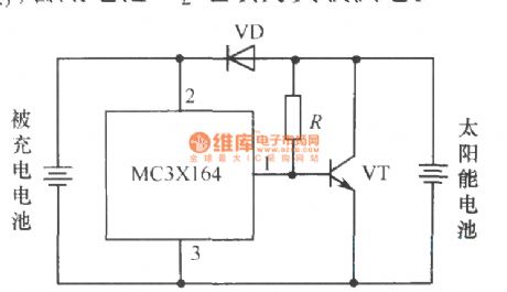
The following circuit illustrates a current-limited solar battery charger circuit diagram. This lead-acid or Ni-Cd battery charger circuit diagram utilizes solar energy to charge a 6-volt, 4.5 Ah rechargeable battery for various applications. It represents a straightforward solar battery...
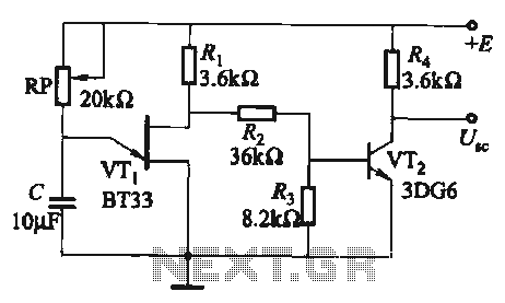
The circuit comprises a single-junction transistor VTi, a resistance Ri, a potentiometer RP, and a capacitor C, forming a relaxation oscillator and an amplifier transistor VTz. The adjustment potentiometer RP allows for changing the relaxation oscillation frequency, providing a...
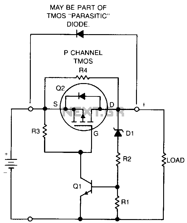
If a NiCad battery is discharged to the point where the lowest capacity cell becomes fully discharged and reverses polarity, that cell will typically short internally and become unusable. To prevent this type of damage, this circuit detects a...