
Time Delay Relay
The time delay relay circuit consists of several key components that work together to provide a timed activation of the relay. The main elements include a resistor (R1), a capacitor (C1), and a switch (S1), which collectively form an RC timing circuit.
R1 serves as the timing resistor, and its value can be adjusted to modify the duration for which the relay remains activated. The time constant of the circuit, which determines the delay period, is influenced by the product of the resistance (R1) and the capacitance (C1). By selecting a suitable capacitor value for C1, the maximum on time can be tailored to meet specific requirements, allowing for flexibility in applications.
The switch S1 initiates the timing sequence. It can be a mechanical switch for manual activation or replaced with an NPN transistor for electronic triggering. This modification enables the circuit to be controlled by a microcontroller or another digital circuit, enhancing its versatility in automated systems.
Upon activation, the capacitor C1 begins to charge through R1. The relay will remain energized until the voltage across C1 reaches a certain threshold, at which point the relay will deactivate. The current capacity of the overall circuit is dictated by the specifications of the relay used; therefore, selecting a relay with appropriate ratings is crucial for ensuring the circuit can handle the intended load.
This time delay relay circuit is ideal for applications requiring a delayed response, such as in lighting control, motor activation, or any system where a timed action is necessary after an initial trigger. Proper design considerations should be taken into account to ensure that component ratings and values align with the desired operational parameters.A time delay relay is a relay that stays on for a certain amount of time once activated. This time delay relay is made up of a simple adjustable timer circuit which controls the actual relay. The time is adjustable from 0 to about 20 seconds with the parts specified. The current capacity of the circuit is only limited by what kind of relay you decide to use. # R1 adjusts the on time. # You can use a different capacitor for C1 to change the maximum on time. # S1 is used to activate the timing cycle. S1 can be replaced by a NPN transistor so that the circuit may be triggered by a computer, other circuit, 🔗 External reference
Related Circuits
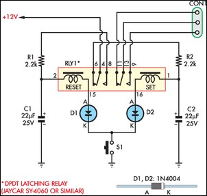
This circuit enables an SPST momentary pushbutton to function as a push-on push-off switch by utilizing a DPDT latching (bi-stable) relay. It was designed to allow a single pushbutton switch on the dashboard of a vintage car to provide...
The human eye is highly skilled at tracking moving objects, a process that occurs effortlessly. This ability relies on the brain's processing power, the rapid response of extraocular muscles, and the light weight of the eyeball. In contrast, a...
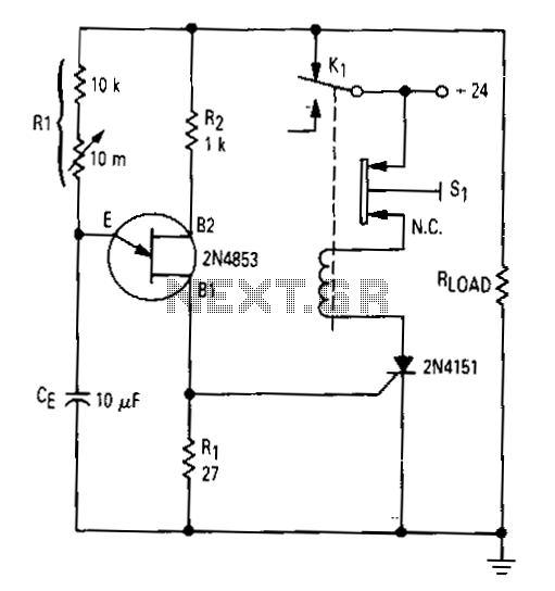
After the first cycle, the relay will normally be energized. When the normally closed pushbutton 51 is activated, the SCR turns off, the relay is de-energized, and power is applied to the relaxation oscillator and the load. After a...
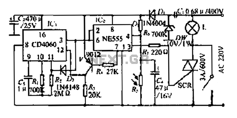
A photosensitive daytime electricity circuit utilizes a very small positive voltage. It features a 555 timer IC with four pins, including a reset pin that operates at low voltage. The circuit includes a bidirectional thyristor (iSCR) that controls lighting,...
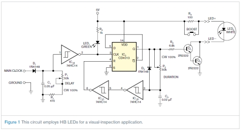
This circuit is not complex, but it was instrumental in an application involving the visual inspection of the spray pattern of fuel injectors for quality and consistency. In this application, xenon strobe lights were unsuitable due to their large...
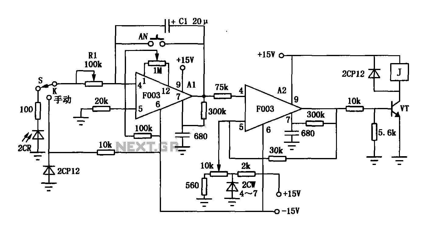
The F003 circuit is a versatile photographic component that functions as an operational amplifier amplifying automatic timer circuit. The operational amplifier A1 serves as an integrator, while operational amplifier A2 is configured as a comparator. A 2CR silicon photocell...
Warning: include(partials/cookie-banner.php): Failed to open stream: Permission denied in /var/www/html/nextgr/view-circuit.php on line 713
Warning: include(): Failed opening 'partials/cookie-banner.php' for inclusion (include_path='.:/usr/share/php') in /var/www/html/nextgr/view-circuit.php on line 713