
time delay relay circuit using 555
No description available.
Related Circuits
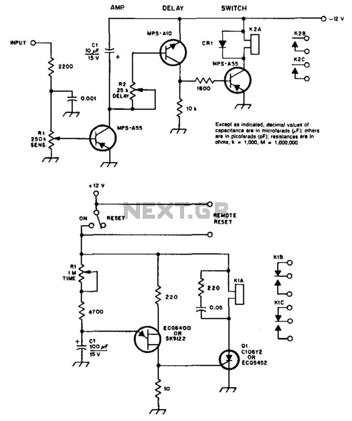
A circuit diagram illustrates a COR/CAS circuit designed for repeater applications. CR1 is identified as a silicon diode, while relay 2 can be any relay with a 12-V coil, with a reed relay being preferred for longevity. Resistor R2...
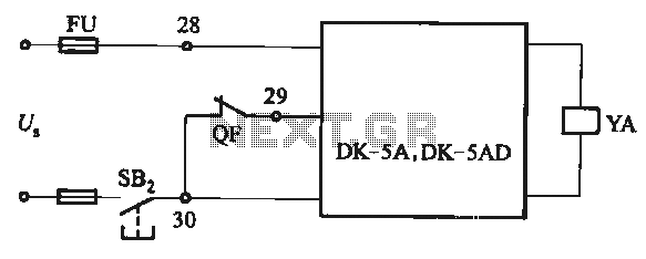
The DK-5A and DK-5AD AC power control circuit is illustrated in Figure 6-77. The figure includes a closing button (SBz) and a line (YA) connected to the closing electromagnet coil (U). This circuit is designed for the operation of...
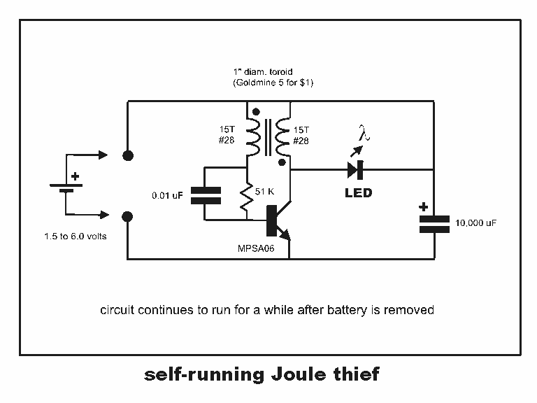
Professor Steven E. Jones' circuit demonstrates an 8x overunity. The concept of overunity refers to a system that produces more energy than is consumed, effectively achieving a coefficient of performance greater than one. In the context of Professor Steven E....
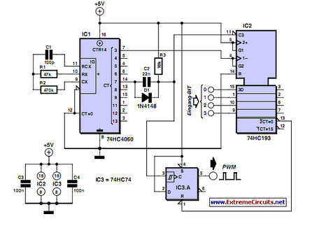
PWM waveforms are frequently utilized to regulate the speed of DC motors. The duty cycle of the digital waveform can be defined using an adjustable parameter. PWM (Pulse Width Modulation) is a technique employed to control the power delivered to...
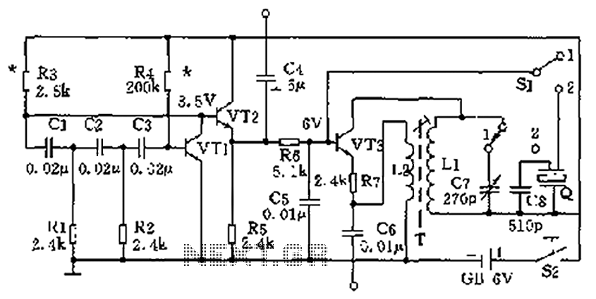
The high-frequency signal generator is designed to produce a low frequency of 1 kHz, an intermediate frequency (IF) signal of 465 kHz, and high frequencies ranging from 525 kHz to 1605 kHz. This device is particularly useful for radio...
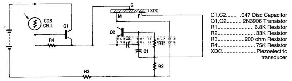
The alarm utilizes a fixed-frequency piezoelectric buzzer alongside a cadmium-sulfide (CDS) cell and a two-transistor circuit to create a distinctive effect. When light reaches the CDS photoelectric cell, the alarm remains silent. However, in the absence of light, transistor...