
Timer and Interrupt
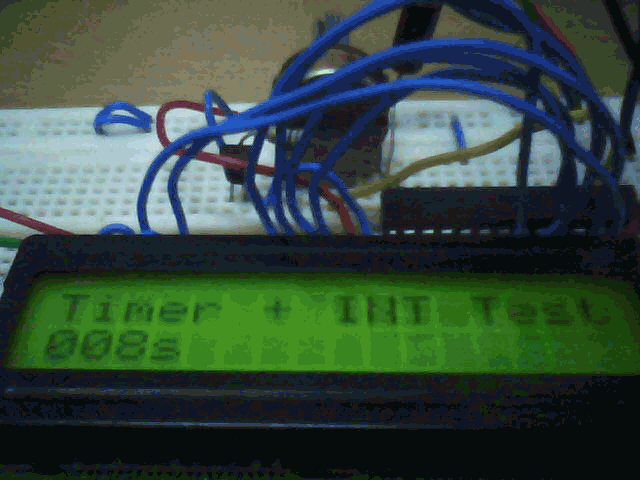
The PIC18 microcontroller features four timers (Timer0 to Timer3) that enable precise timing events, essential for various applications, including event counting and generating delays. This example focuses on Timer0, which is configured to create a one-second interval for an LCD display application. The LCD's backlight will blink every second, and a counter displayed on the LCD will increment until it reaches 199, at which point it will reset to zero.
To achieve a one-second timer overflow, Timer0 is set to operate in 16-bit mode, which allows for a larger counting range. The prescaler is set to 64, which divides the clock frequency to extend the timer's counting duration. Given that the PIC18 operates at an 8 MHz clock frequency, the reload value for Timer0 is calculated to be 34286 (0x85EE in hexadecimal). The calculation for the timer overflow time is derived from the formula:
\[ \text{Time per count} = \frac{1}{\text{Clock Frequency} / \text{Prescaler}} \]
Thus, the total time for the timer to overflow is calculated as follows:
\[ (65536 - 34286) \times \left( \frac{1}{8000000 / 4} \right) \times 64 = 1 \text{ second} \]
The code implementation involves setting Timer0 with the calculated reload value and configuring the interrupt service routine (ISR) to handle timer overflows. Since the C18 compiler does not automatically generate an ISR, a `goto` instruction is used at the interrupt vector to redirect to the appropriate ISR. The high-priority ISR is defined at memory address 0x08, where the interrupt is redirected.
Within the ISR, Timer0 is reloaded with the value 34286 to ensure that the one-second interval is maintained. Additionally, a flag is set within the ISR to signal the main program to update the LCD display. This structured approach ensures accurate timing and efficient operation of the system, allowing for real-time updates to the LCD based on the timer's overflow events.There are 4 timers in PIC18 which are timer0 to timer3. Timers are used when precise timing event need to be generated. Timers are usually used in conjunction with interrupt to keep the timing accurate. This guide will show an example of using timer0 to count a timer for every second. The circuit used for this example is the same as the circuit used in the PWM guide. The back light of the LCD will blink on and off every second, while the counter on the LCD will increase until it reaches 199 then reset back to 0. The counting of second is implemented using an interrupt service routine. The guide will be divided in to 2 parts, 1st part dealing with the setting on Timer0 and the second on the interrupt service routine.
The first part would be setting up the timer to overflow every 1s. Timer overflow occurs when TMR0 go froms 0xFFFF to 0x0000. Since the PIC is running at 8Mhz, the reload needed for the timer can be calculated. To achieve overflow 1s the timer will be set in 16 bit mode. Prescaler of timer0 is set to 64 and the reload value to 34286 or 0x85EE. With this value 1s overflow can be achieved. The calculation below give the time taken for the overflow with TMR0 set to 34286. (1 / (8 000 000 / 4)) * 64 is the time for each count of timer0. (65 536 - 34 286) * (1 / (8 000 000 / 4)) * 64 = 1 Code below is used to set the timer in to the required reload value and mode. Since that C18 does not create ISR automatically, a goto instruction must be created at the vector to redirect the interrupt to the appropriate ISR.
In this example only the high priority ISR is used, the code below shows the setting for the ISR. A code section is created at 0x08 which is the high interrupt vector to redirect the interrupt to the ISR. Inside the ISR the timer period is reloaded back to 34286 so that 1s interrupt can be achieved. check is set in the ISR to tell the main program to update the LCD. 🔗 External reference
Related Circuits
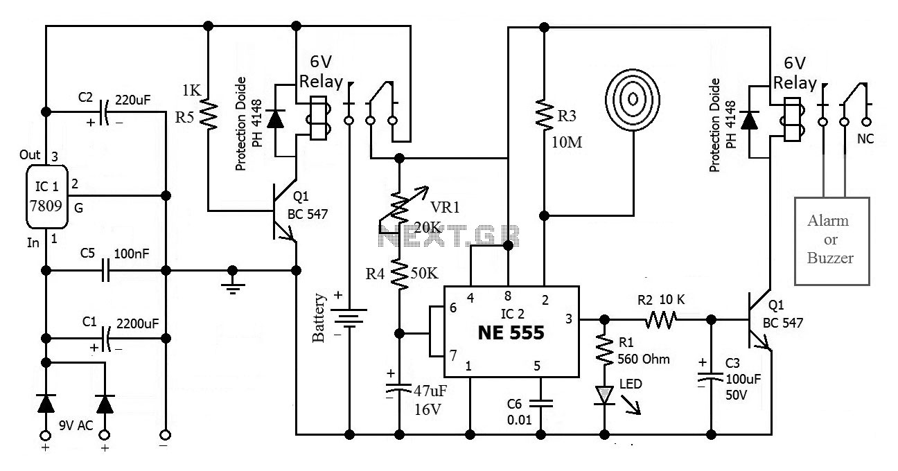
This is the circuit diagram of a touch-activated alarm system that remains operational during power outages. The alarm system is triggered when someone touches the designated touch plate. A notable feature of this circuit is the automatic battery activator,...
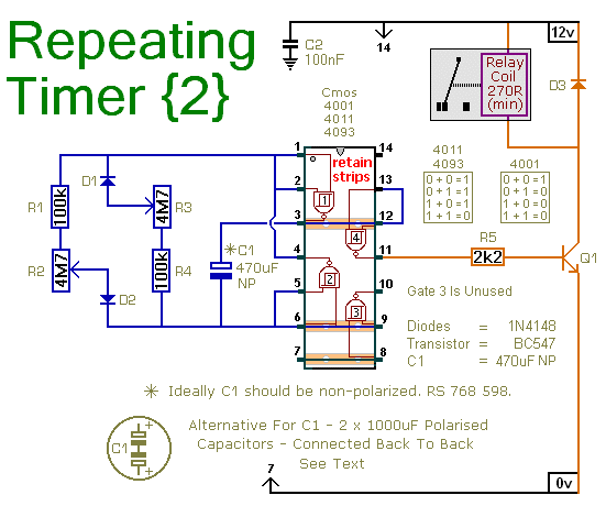
This circuit is based on a simple asymmetric oscillator. The duration for which the relay remains energized and the duration for which it remains de-energized are independently set. With the component values indicated in the diagram, both durations are...
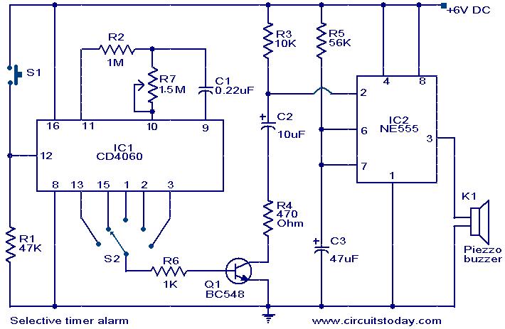
A timer circuit utilizing the IC 4060 is presented. The IC 4060 functions as a 14-stage binary counter equipped with an integrated oscillator. The components R2, R7, and C1 are responsible for determining the oscillator's frequency, causing the outputs...
A programmable clock timer circuit that utilizes individual LEDs to indicate hours and minutes. Twelve LEDs can be arranged in a circle to represent the twelve hours of a clock face, while an additional twelve LEDs can be arranged...
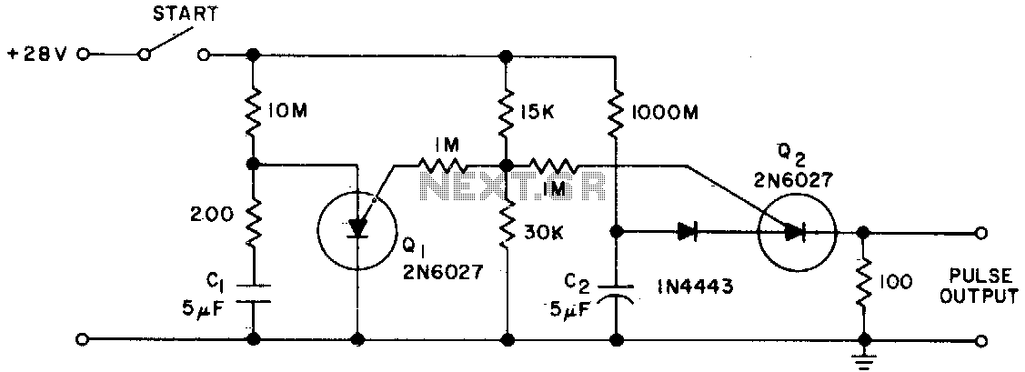
The Programmable Unijunction Transistor (PUT) serves as both a timing element and a sampling oscillator. A low leakage film capacitor is required for capacitor C2 because of the minimal current supplied to it. The Programmable Unijunction Transistor (PUT) is a...
This device is designed to maintain a deep cycle battery using energy harvested from a solar panel. It functions as a combination of a digital clock timer and a solar panel charge controller. Component: .. This circuit serves the dual...