
Controlling Motor Starting
Motor starters are essential components in industrial and commercial electrical systems, serving to control the operation of electric motors. The two primary types of motor starters, full-voltage and reduced-voltage, are chosen based on specific operational requirements and system constraints. Full-voltage starters are designed for direct connection, allowing motors to start at the line voltage, which is often suitable for smaller motors or applications where high starting torque is not a concern. However, for larger motors or those with significant load inertia, reduced-voltage starters are preferred to mitigate the adverse effects of high inrush current and mechanical stress on connected equipment.
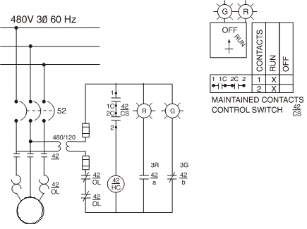
The schematic for a full-voltage starter typically includes a contactor, overload relay, and control circuit components such as push buttons for start and stop functions. The contactor serves to connect the motor to the power supply when energized, while the overload relay protects the motor from overheating by disconnecting the circuit in case of excessive current draw. The control circuit often features auxiliary contacts that provide feedback to the operator regarding the status of the motor.
In contrast, reduced-voltage starters may employ methods such as autotransformers, star-delta configurations, or soft starters to gradually ramp up the voltage applied to the motor. These configurations effectively limit the starting current and reduce mechanical shock, thereby enhancing the longevity of both the motor and the driven equipment. The schematic for a reduced-voltage starter will incorporate additional components to manage the transition from low to full voltage, ensuring a smooth acceleration profile.
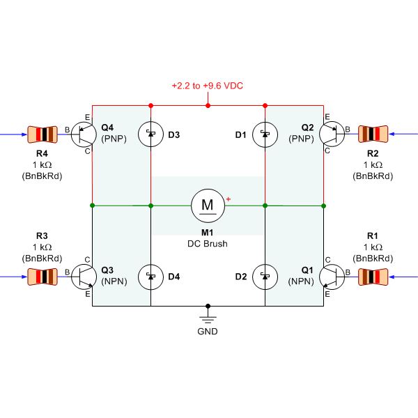
Furthermore, the selection of motor starters must take into account the characteristics of the electrical supply system, including voltage stability and load conditions. The motor's starting characteristics, such as locked rotor current and torque requirements, must also be evaluated to ensure compatibility with the chosen starter type. Proper coordination between the starter and the motor is crucial to achieving reliable operation while minimizing the risk of electrical disturbances that could affect the overall system performance.Motor starters generally fall into two categories: full-voltage or reduced-voltage. The choice of which type of starter to use depends on various factors, such as current-carrying capacity of plant wiring, ability of plant power supplies to absorb power transients, size of the motor, and other special control requirements. The first type to be covered is the full-voltage starter. Full-voltage starters, sometimes referred to as ``across-the-line`` starters, are the most widely used type of starter. A starter of this type, shown in ```Figure 1```, directly connects the motor leads and line leads together through either a manual starter or the main line contacts of a magnetic starter and does not provide any means of reducing the applied voltage or limiting the starting current.
The full-voltage starter is used on almost all three-phase, squirrel-cage, and single-phase machines. The use of this type of starter for squirrel-cage motors is limited by the strain imposed on the installed wiring systems and by the starting current and torque when the motor is first energized.
Whenever the starting of a motor at full voltage would cause serious and unacceptable voltage transients or excessive torque when unneeded, reduced-voltage starters are used to reduce the starting transients. There are, however, other reasons for using this type of control. The effect on the equipment must be taken into account in the selection of motor starters. When a large motor is started across the line, it puts a tremendous strain or shock on such things as gears, fan blades, pulleys, and couplings.
When the load is heavy and hard to bring up to speed, reduced-voltage starting may be necessary. Belt drives on heavy loads are apt to have excessive slippage unless the torque is applied slowly and evenly until full speed is reached. Overload devices have become increasingly reliable, giving the motor every opportunity to make a safe start.
Using reduced voltage in an attempt to prevent overheating during starting and acceleration is a wasted effort. The acceleration time will increase, and the overloads will still trip. Reduced-voltage starting lowers the applied starting torque, thus minimizing the shock on the driven machines.
Regardless of the method used to reduce the voltage to a motor, it must be kept in mind that the current will also be reduced, as will the torque. With this in mind, it becomes apparent that a motor that will not start on full voltage at a given load will also not start under the same load at a reduced voltage and subsequent reduced current.
Any attempt to use a reduced-voltage starter will not be successful in accelerating troublesome loads. As voltage is reduced, current is reduced proportionally; however, torque decreases with the square of voltage.
Example: At 70 percent applied voltage, find the percentage of starting current for a standard motor that draws six times normal full-load running current. One of the most common functions of reduced-voltage starting is to reduce the starting current of induction motors.
The rate-of-change of starting current is confined to prescribed limits. In other words, the motor presents a predetermined, current-time picture to the supply system. This current-time picture for a given area is maintained and regulated by the utility company serving the area. The power company will attempt to maintain a reasonably constant voltage at points of supply so that lights do not dim or flicker noticeably.
The success of the power company in this attempt depends on the generating capacity to the area, including transformer and line-loading conditions and adequacies as well as automatic voltage regulating equipment. Transient overloading of the power supply may be caused by sudden high surges of reactive current from large motors on starting and by pulsations in current taken by electrical machinery driving reciprocating compressors or X-ray equip
🔗 External reference
Related Circuits
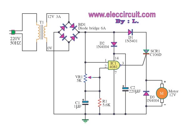
This is a speed motor controller circuit for a 12V DC motor. The speed of rotation of the spindle motor can be adjusted from 5 to 60 cycles per minute. The speed motor controller circuit for a 12V DC motor...
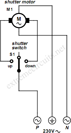
An electrically operated rolling shutter typically features a standard control panel equipped with a three-position switch: up, down, and stop. To automate the opening and closing of the shutter using a time-controlled switch, additional wiring connections are necessary. The...

Controlling the speed of a three-phase AC motor is achieved by regulating the frequency of the power supply, as the motor operates in synchronization with the line frequency. A three-phase AC motor speed controller functions as a three-phase sine...
PID-Control with 68HC11. STEPPER CONTROL. 68HC11 read encoder. High accuracy RPM-measurement with 68HC11. The encoder is connected to PORTA PA0 and PA1. The board must be in BOOTSTRAP MODE (tested with Loggyboard). The circuit utilizes a 68HC11 microcontroller for implementing...
Selecting the appropriate DC motor is essential for constructing mobile robots. Testing DC motors is straightforward and can be accomplished by assembling a basic DC motor circuit. The components needed for this circuit include a DC motor, a battery...
A request has been made to automate certain functions within a residence, specifically to control the on and off states of CFL lamps using a triac that is coupled to a logic circuit via a zero-crossing detection mechanism. To achieve...