
Tiny pH-meter
The pH meter circuit is designed to measure the acidity or alkalinity of a solution through a glass electrode probe. The compact design, measuring only 11 cm², incorporates a power supply unit (PSU) that operates at a reduced voltage of +/-5V, making it suitable for portable applications and reducing power consumption compared to traditional +/-12V systems.
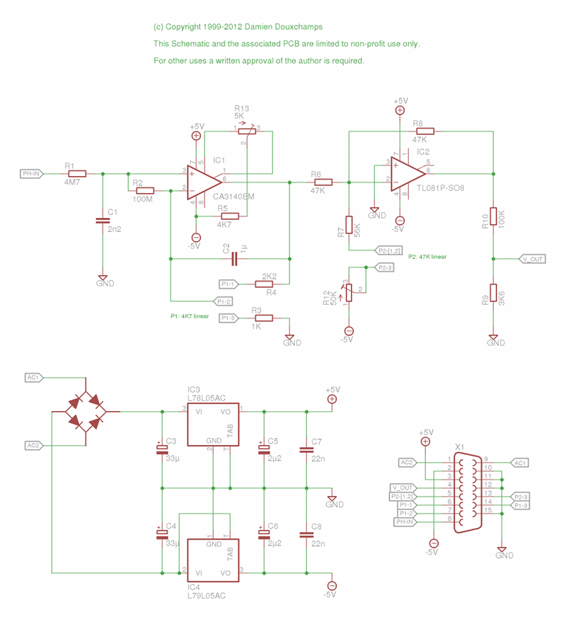
The circuit begins with the pH probe connected to pin 15 of connector K1. The probe generates a voltage that corresponds to the pH level of the solution. This signal is then fed into IC1, a CMOS operational amplifier (op-amp), which is chosen for its high input impedance. This characteristic is crucial as it prevents loading the probe, ensuring accurate readings.
To filter out high-frequency noise that could interfere with the measurement, the signal passes through an RC (resistor-capacitor) circuit before reaching the op-amp. This low-pass filter configuration allows only slow variations in the signal to be processed, effectively eliminating unwanted high-frequency noise or parasitic signals that could skew results.
The gain of IC1 is set to amplify the weak signal from the pH probe to a usable level for further processing or display. The design ensures that the op-amp operates within its optimal range, preserving the integrity of the pH measurements.
The compact PCB layout has been optimized for minimal space usage, which is a significant consideration given that PCB costs are often determined by surface area. This design has proven reliable over several years of usage in educational settings, demonstrating its effectiveness in teaching and practical applications. Overall, this pH meter represents a blend of innovative engineering and practical design, making it a valuable tool for both educational and experimental purposes.This tiny pH-meter is very tiny: 11cm2 including the PSU circuit! I built it for the College Saint Pierre a few years ago. It is based on a circuit developped at the Facultes Notre-Dame de la Paix, Namur, Belgium. I modified several components to allow a smaller power supply (+/-5V instead of +/-12V) which could be used to power the display unit. I also spent `some time` fitting everything on a very small PCB, just for the fun of it (and also because PCBs are sold per cm2 of surface).
At this time about 30 have been built and used for several years during college classes, demonstrating their reliability. The circuit input is pin 15 of K1. The probe signal enters IC1 via an RC circuit designed to allow only relatively slow signal variations (and avoid getting parasite HF signals). IC1 is a CMOS op-amp and thus has a very high impedance. The gain of IC1 is 🔗 External reference
Related Circuits
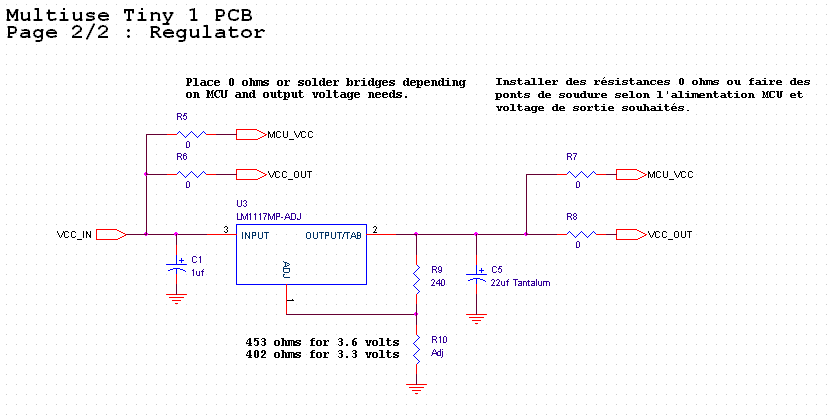
This small PCB, named Multiuse Tiny1, was originally designed to convert NES/SNES controllers to USB. Given the limited space inside an SNES controller, the PCB was designed to be as compact as possible. The design has evolved over time,...
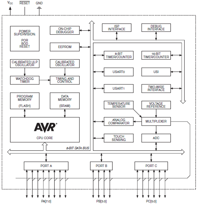
The ATtiny1634 8-Bit AVR Microcontroller from Atmel is based on the enhanced RISC architecture of AVR. It can execute powerful instructions in a single clock cycle, achieving throughputs close to 1 MIPS per MHz. This allows system designers to...
This firmware is intended to run on an Atmel ATtiny2313 operating from a 4, 8, 10, 16, or 20 MHz clock or an AT90S2313 operating from a 4 MHz clock. As far as I have been able to determine,...
Loop Antennas are considered to be small when their diameter drops below about 1/10 of the wavelength they are intended to be used at. In this case, the term "Tiny" is used because the antenna's diameter is about 1/30,000...
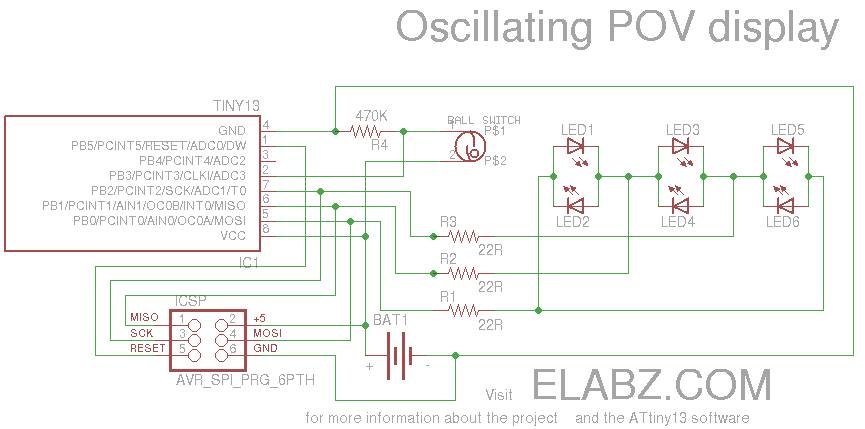
Smart Valentine's Day gift - a movement-sensing box of chocolates with an LED message. Circuit diagram and instructions for building the project using ATtiny13 and Arduino. The project involves creating a movement-sensing box of chocolates that incorporates an LED display...

Usually we see Digital clock on LCD or 7 segment. But, this AVR Digital Clock which is designed by Ficara Emilio displayed on Oscilloscope. The project uses ATtiny 2313 as the main controller. What an interesting microcontroller project. Source...