
Q- Multiplying Loop Antenna
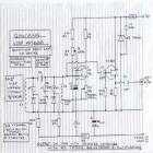
The described circuit is intended for use with a standard 4-foot square loop antenna, optimized for medium wave (MW) radio reception over long distances. The square loop antenna is characterized by its simplicity and effectiveness in capturing electromagnetic waves, particularly in the MW frequency band.
The circuit typically consists of an impedance matching network to ensure maximum power transfer from the antenna to the receiver. This network can include components such as capacitors and inductors arranged in a specific configuration to resonate at the desired frequency range.
Additionally, the circuit may incorporate a low-noise amplifier (LNA) to enhance the weak signals received by the loop antenna. The LNA is strategically placed close to the antenna to minimize signal loss due to cable attenuation. The output of the LNA can be fed into a bandpass filter, which helps to eliminate unwanted frequencies and noise, ensuring that only the desired MW signals are processed.
Power supply considerations are also crucial, as the circuit should be designed to operate efficiently with low power consumption, particularly if it is intended for portable or remote applications. The power supply circuit may include voltage regulators to provide stable operating conditions for the LNA and other active components.
Overall, this circuit design is aimed at improving the performance of medium wave reception, utilizing the unique characteristics of the 4-foot square loop antenna for optimal signal capture and processing.This circuit is designed to be used in conjunction with the standard 4 foot square loop used in MW for long distance reception. 🔗 External reference
Related Circuits

This is a circuit for Closed-Loop Automatic Power Control for RF Applications. The circuit utilizes a log detector (AD8318) and a variable gain amplifier (VGA) (ADL5330). The Closed-Loop Automatic Power Control (APC) circuit is designed to maintain a consistent output...
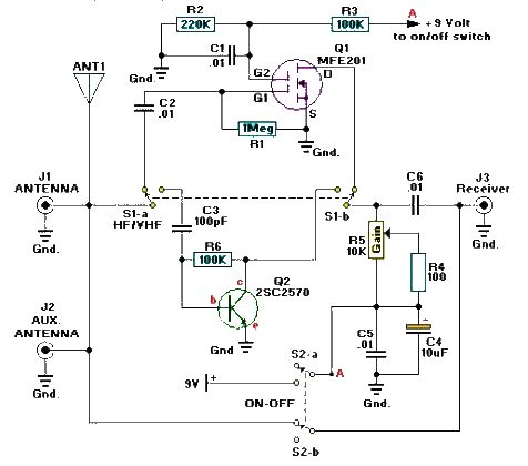
A simple and efficient active antenna electronic project can be designed using this electronic schematic circuit based on transistors. This active antenna project is effective for a wide range of RF frequencies, covering three RF bands: HF, VHF, and...
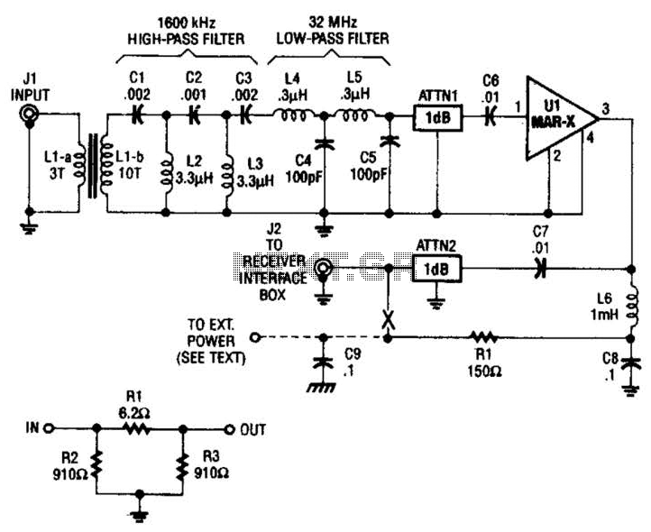
The HF/SW receiver preamplifier consists of a broadband toroidal transformer (LI-a and Ll-b), an LC network featuring a 1600-kHz high-pass filter and a 32-MHz low-pass filter, inductors L2 and L3 (26 turns of #26 enameled wire wound on an...
This new loop antenna designed by Graham Maynard features a six-foot square, six-turn loop that is aperiodic in nature, covering a frequency range of 50 KHz to 5000 KHz. Its size allows for inconspicuous mounting against a garden fence,...
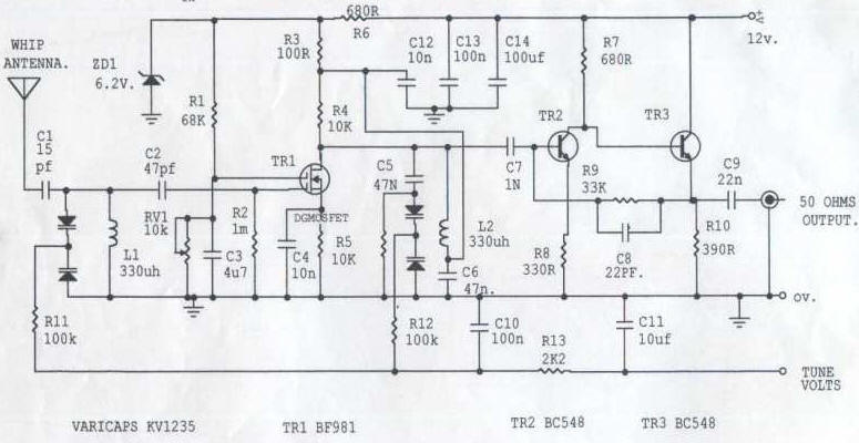
This circuit is designed to amplify the input from a telescopic whip antenna. The preamplifier is intended to operate within the medium waveband, covering frequencies from approximately 550 kHz to 1650 kHz. The required tuning voltage ranges from 1...
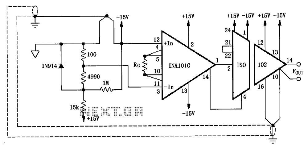
The circuit, as illustrated in the figure, consists of an ISO102 and an INA101 designed to eliminate ground loops and provide high-end cold junction compensation for a thermocouple amplifier. This configuration utilizes a K-type thermocouple to detect temperature at...