
Using current quick break and overcurrent protection circuit overcurrent relay a sensor

The schematic in Figure 4-52 (a) represents a two-phase wiring configuration suitable for DC applications. This setup typically involves two distinct phases, each supplying power to a load. The two-phase system allows for a more efficient use of conductors, reducing the amount of copper required compared to single-phase systems. In DC operation, the current flows in one direction, and the circuit components must be rated to handle the continuous voltage and current without overheating or failing.
In contrast, Figure 4-52 (b) showcases a two-phase current differential wiring configuration intended for AC applications. This design is particularly advantageous for systems that require differential current sensing, such as in protective relays or current transformers. In AC operation, the current alternates direction, necessitating components that can handle alternating voltages and currents effectively. The differential wiring arrangement helps to isolate faults and enhances the safety and reliability of the electrical system.
Both configurations emphasize the importance of proper component selection, including switches, connectors, and protective devices, to ensure optimal performance and safety in their respective applications. The choice between DC and AC wiring will largely depend on the specific requirements of the application, including load characteristics and the intended use of the electrical system.Figure 4-52 (a) for the two-phase wiring, DC operation; Figure 4r52 (b) for the two-phase current differential wiring, AC operation.
Related Circuits
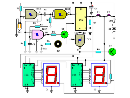
This circuit measures the distance covered during a walk. The hardware is housed in a small box that can be placed in a pocket, and the display is designed as follows: the leftmost display D2 (the most significant digit)...
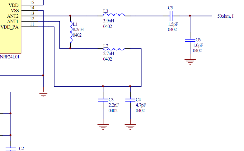
Place the transceiver and the chip antenna very close together, eliminating the need for a 50-ohm transmission line. If this is the case, can the two matching circuits be merged into one to reduce the component count? To create an...
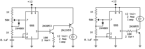
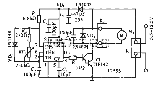
The schematic diagram illustrates a 12 Volt Car Lamp Dimmer Circuit Design utilizing a 555 Timer. This circuit can be employed to dim a standard 25-watt lamp. The 12 Volt Car Lamp Dimmer Circuit utilizes a 555 Timer in astable...
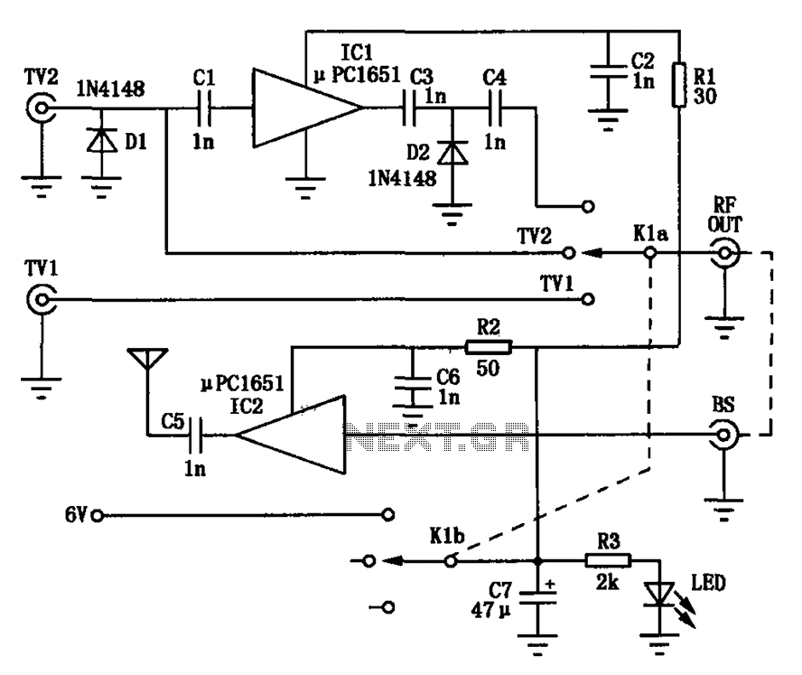
Amplification is utilized to convert video output signals from various devices, such as VCRs and DVD players, which often require amplification of weak output signals. Additionally, it can transmit radio frequency signals over a radius of approximately 7 meters,...
The circuit operates using pulse position modulation, which is a method distinct from the more commonly utilized pulse width modulation for speed control. A 555 timer is employed as a square wave modulator, generating output pulses with a fixed...
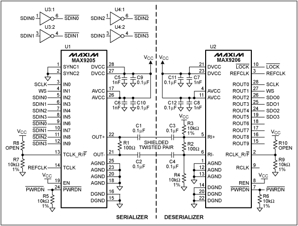
This application note outlines the transmission of I²S audio data streams between two audio components using a single shielded twisted-pair (STP) wire, employing the MAX9205 10-bit LVDS serializer and the MAX9206 10-bit LVDS deserializer. Low-voltage differential signaling (LVDS) serves...