
Tone Oscillator with 555

The circuit operates using a 555 timer configured in astable mode to generate a square wave output. The frequency of oscillation is determined by the resistors R1 and R2, and the capacitor C. In this configuration, R1 is set at 1 kΩ while R2 is set at 6.2 kΩ, leading to a frequency of approximately 1 kHz. The output from the 555 timer is not suitable for directly driving a speaker due to current limitations; therefore, an NPN transistor is employed to amplify the current. The transistor acts as a switch, allowing higher current to flow through the speaker while the 555 timer output controls the base of the transistor.
A capacitor connected to the base of the transistor serves to stabilize the switching action, minimizing voltage spikes that could be generated by the inductive load of the speaker. The choice of a small capacitor value is critical in managing the rise and fall times of the output signal, ensuring a cleaner square wave is delivered to the speaker.
For applications requiring lower frequencies, the value of R2 can be increased, which will lower the overall frequency of oscillation. Conversely, for higher frequencies, a reduction in the capacitance value will be necessary, as R1 has a minimum threshold that cannot be reduced significantly below 1 kΩ without affecting the circuit's performance.
To control the volume of the output sound, a resistor can be placed in series with the speaker, allowing for adjustments from 10 to 100 ohms based on desired loudness. In an alternative configuration where the speaker is driven directly from the timer output, a series capacitor (100 µF) is used to couple the AC signal to the speaker. This capacitor allows the speaker to be driven with an AC waveform, enhancing sound production as it allows current to flow in both directions, rather than the pulsating DC that would occur without it. A 51-ohm resistor is included to limit the current to a safe level for the 555 timer, ensuring that it operates reliably at a supply voltage of 9 volts. At a lower supply voltage, such as 4.5 volts, the resistor value can be adjusted accordingly to maintain proper operation.This is a basic 555 squarewave oscillator used to produce a 1 Khz tone from an 8 ohm speaker. In the circuit on the left, the speaker is isolated from the oscillator by the NPN medium power transistor which also provides more current than can be obtained directly from the 555 (limit = 200 mA). A small capacitor is used at the transistor base to slow the switching times which reduces the inductive voltage produced by the speaker.
Frequency is about 1.44/(R1 + 2*R2)C where R1 (1K) is much smaller than R2 (6.2K) to produce a near squarewave. Lower frequencies can be obtained by increasing the 6.2K value, higher frequencies will probably require a smaller capacitor as R1 cannot be reduced much below 1K. Lower volume levels can be obtained by adding a small resistor in series with the speaker (10-100 ohms).
In the circuit on the right, the speaker is directly driven from the 555 timer output. The series capacitor (100 uF) increases the output by supplying an AC current to the speaker and driving it in both directions rather than just a pulsating DC current which would be the case without the capacitor. The 51 ohm resistor limits the current to less than 200 mA to prevent overloading the timer output at 9 volts.
At 4.5 volts, a smaller resistor can be used. 🔗 External reference
Related Circuits
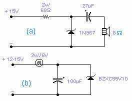
These two circuits are interesting from an academic point of view. Their practical implementation is rather critical and it is not easy to get steady operation. Circuit (a) requires a "cooked" zener: connect it first to a constant current...
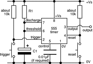
The 8-pin 555 timer is one of the most versatile integrated circuits (ICs) available, utilized in numerous projects. With minimal external components, it can be employed to construct various circuits, many of which do not pertain to timing applications....

A common issue in crystal sinusoidal oscillators is the excitation of unintended modes of the quartz crystal, which diminishes the spectral purity of the oscillator. This issue is particularly significant in overtone crystals, especially for low-voltage applications. In such...
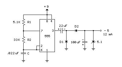
A 555 timer can be used to generate a square wave to produce a negative voltage relative to the negative battery terminal. When the timer output at pin 3 goes positive, the series 22 uF capacitor charges through the...
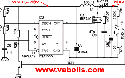
The following circuit illustrates a low voltage power supply (PSU) for Nixie tubes utilizing a 555 Timer integrated circuit (IC). The coil used in this schematic is purchased from a store. The described circuit operates as a low voltage power...
This is a resistance-tuned oscillator that operates in three frequency ranges from 35 cycles per second (cps) to 35,000 cps. A significant challenge with resistor/capacitor tuned bridges is maintaining a constant output level across a full decade frequency range....