
Stereo Tone Control using LM1036
The stereo tone control circuit utilizing the LM1036 IC is designed to enhance audio playback quality by allowing users to adjust sound characteristics to their preferences. The LM1036 is a dual-channel tone control IC that provides a versatile solution for audio applications. The circuit typically consists of a power supply section, tone control section, and output stage.
The power supply section should provide a stable DC voltage within the specified range of 9V to 15V. This can be achieved using a linear voltage regulator or a switching power supply, depending on the design requirements and efficiency considerations.
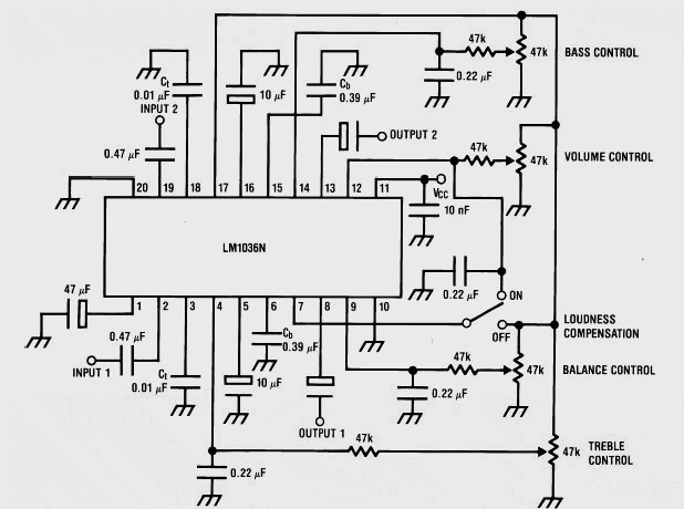
In the tone control section, the LM1036 IC is configured with external capacitors that define the frequency response for bass and treble adjustments. The choice of capacitors determines the cutoff frequencies for each tone control feature. Capacitors connected to pins 3 and 18 will influence the treble response, while those connected to pins 6 through 15 will affect the bass response. The values of these capacitors can be selected based on the desired tonal characteristics, allowing for customization of the audio output.
The volume control is typically implemented using a potentiometer, which adjusts the overall signal level before it reaches the output stage. The balance control can also be implemented using a dual-gang potentiometer, allowing for independent adjustment of the left and right channels.
The output stage may include additional amplification or buffering to drive speakers or headphones effectively. Proper grounding and layout considerations are essential to minimize noise and ensure high-quality audio performance.
This tone control circuit can be integrated into various audio systems, enhancing the listening experience by allowing users to tailor the sound to their liking. It is particularly useful in environments where audio quality is paramount, such as home theaters, car audio systems, and professional audio equipment.Welcome to the weblog where we discuss about electronic circuits schematics, PCB design, diy kits and electronic projects diagrams. This a stereo tone control circuit built using LM1036 IC. This control circuit bass / treble tone level, volume and balance between the right channel and left channel (Input 1 and 2).
You can use this circuit for ste reo applications such as car radio, television and audio systems, MP3 player, DVD player, ipod and more. An additional control input allows loudness compensation to be made simply. The circuit must be working with a supply voltage of 9V to 15V DC. Each tone response is defined by a single capacitor chosen to give the desired characteristic. By changing the values of capacitors connected to the tone control unit, you can control bass and treble levels.
pin 3 and pin 18 of IC are for acute and pin 6 to pin 15 for bass. 🔗 External reference
Related Circuits
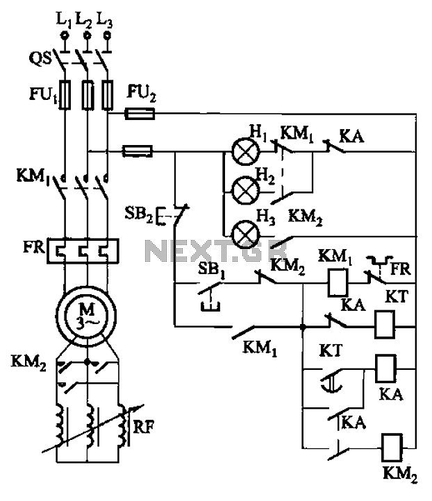
The circuit depicted in Figure 3-165 utilizes a time relay (KT) for controlling the start-up time. Indicator light Hi serves as the power indicator, H2 is designated for the start lights, and H3 functions as the running lights. The circuit...
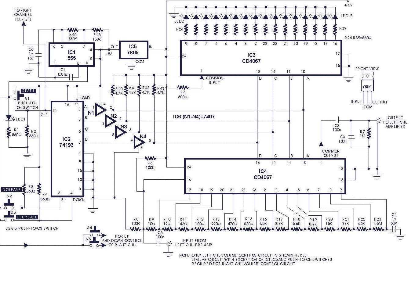
Circuit of a digital volume control using six discrete ICs, including a 5V regulator, is presented. IC1 (555) is configured to function as astable flip-flop. Its frequency or period may be adjusted by proper choice of resistors R44, R45...
Variable-gain amplifiers (VGAs) can be used in many types of systems, such as radio receivers. In this system, the input signal voltage depends on an. Variable-gain amplifiers (VGAs) are integral components in various electronic systems, particularly in radio receivers where...
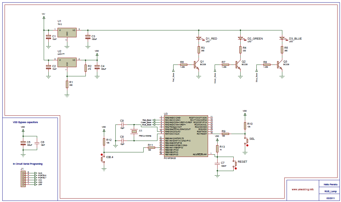
In this project it was used the Piranha Super-flux RGB Led of common anode, and the PIC18F25K20, in order to generate combinations of colors. It has two function modes, automatic that generate the color sequence that is stored in...
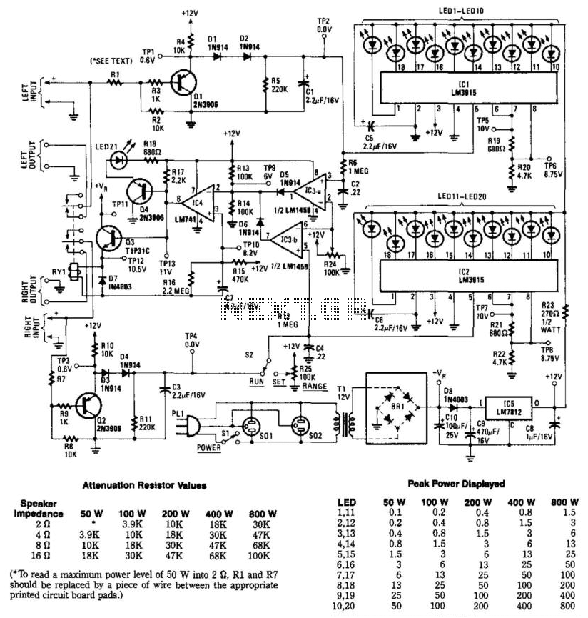
This circuit is designed to measure the audio power output of an amplifier connected to a speaker. Relay RY1 is activated when excess power is delivered to the speaker. The circuit includes two channels for stereo applications. Resistors R1,...
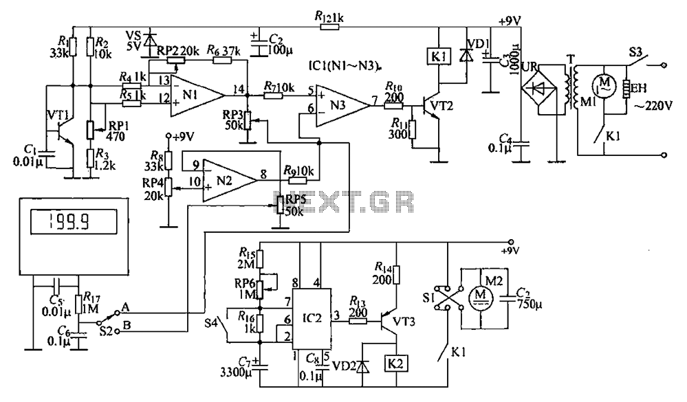
The circuit is illustrated. It includes a DC power circuit with a power switch (S3) that converts 220V AC voltage through a buck converter (T), a rectifier (UR), and filter capacitors (C3 and C4) to generate a +9V output....
Warning: include(partials/cookie-banner.php): Failed to open stream: Permission denied in /var/www/html/nextgr/view-circuit.php on line 713
Warning: include(): Failed opening 'partials/cookie-banner.php' for inclusion (include_path='.:/usr/share/php') in /var/www/html/nextgr/view-circuit.php on line 713