
Touch sensor switch using inverters
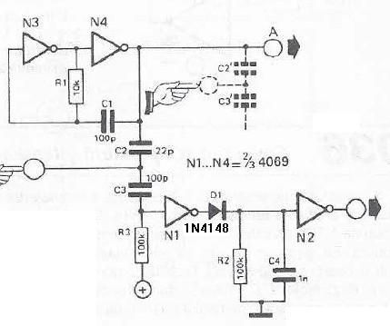
The circuit employs two inverters, N1 and N2, which are essential for signal processing. The oscillator, composed of N3 and N4, generates a continuous 1 MHz square wave signal that serves as the input for the first inverter, N1. The touch sensor is designed to detect changes in capacitance when a hand approaches, effectively altering the input signal at N1. This change is crucial as it determines the logical state at the output of N2.
When the sensor is inactive, the signal from the oscillator maintains a logical high state at N1, which in turn keeps N2 outputting a logical '1'. The introduction of a hand near the sensor modifies the capacitance, creating a capacitive coupling to ground. This coupling reduces the input voltage at N1, leading to a drop in the output state of N2 to logical '0'.
Upon removing the hand from the sensor, capacitor C4 begins to charge through diode D1, allowing for a brief delay before the output of N2 returns to logical '1'. This delay is significant for applications requiring a momentary response to touch, providing a clear indication that the sensor was activated. The diode D1 plays a crucial role in ensuring that the charge does not discharge too quickly, thereby maintaining the output state for a short duration after the touch is released.
Overall, this touch sensor switch circuit is a practical example of how capacitive sensing can be implemented using basic electronic components, offering a reliable solution for touch-sensitive applications.This touch sensor switch can is designed using inverters (N1, N2)and some common electronic components. In standby state at the entrances of N1 there is a signal produced by oscillator N3/N4. At the touch sensor hand capacity forms a bridge to the ground for the 1MHz signal so that the voltage signal at the entrance of N1 decreases more (at the ex
it of N2 is logical 1). After the release of contact, a signal charge C4 through D1 Mhz, so the output of N2 is 0 logic after short time. 🔗 External reference
Related Circuits
Voltage regulator ICs from the 78xx series deliver a stable output voltage in contrast to a highly variable input supply, provided that the common terminal is grounded. Any voltage applied above zero volts (ground) to the common terminal is...

A Siemens SLB0586A IC enables the creation of a straightforward touch-controlled dimmer circuit. This circuit regulates a triac AC switch, allowing control of loads ranging from 10 to 400 W. The Siemens SLB0586A integrated circuit is designed to facilitate the...
A circuit has been constructed based on a design from Silicon Chip magazine to test bipolar stepper motor collections. The circuit is easy to build and functions effectively. The described circuit is designed to facilitate the testing of bipolar stepper...
This month I am making 3 different types of siren circuits based on the 555 timer. The first circuit simulates the siren of a British police car. It uses two 555 timers in the circuit. The 555 on the...
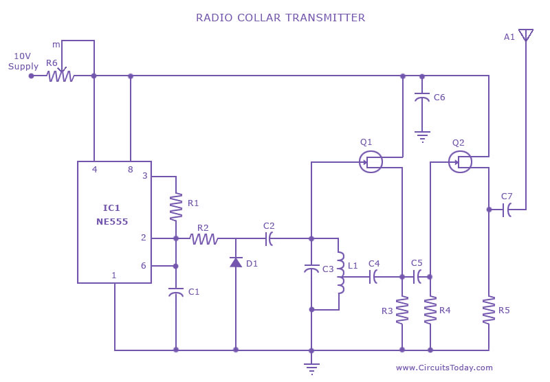
This is a radio transmitter circuit diagram designed for integration into radio collars using the NE 555 integrated circuit. The circuit transmits a pulse in the FM band, specifically between 88 MHz and 105 MHz. The radio transmitter circuit utilizes...
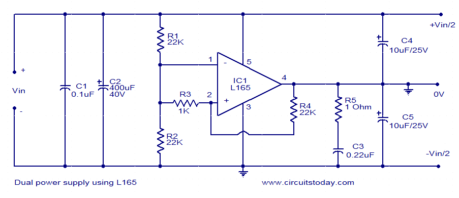
This dual power supply utilizes the L165 power operational amplifier from SGS-Thomson Microelectronics. The L165 IC can deliver up to 3.5A of current, with internal current limiting. It is available in a Pentawatt package, making it well-suited for power...
Warning: include(partials/cookie-banner.php): Failed to open stream: Permission denied in /var/www/html/nextgr/view-circuit.php on line 713
Warning: include(): Failed opening 'partials/cookie-banner.php' for inclusion (include_path='.:/usr/share/php') in /var/www/html/nextgr/view-circuit.php on line 713