
Using ULN2003 to drive a bipolar stepper motor

The described circuit is designed to facilitate the testing of bipolar stepper motors, which are widely used in various applications due to their precise control and reliability. The schematic typically includes a power supply section, a control interface, and a driver circuit tailored for bipolar stepper motors.
The power supply section usually consists of a regulated DC source capable of delivering the necessary voltage and current to the stepper motors. It is essential to ensure that the power supply can handle the motor's specifications to prevent damage during operation.
The control interface may involve a microcontroller or a simple switch mechanism that allows the user to select different stepping modes, such as full-step, half-step, or wave drive. This selection can be achieved through a combination of resistors and capacitors that define the timing and sequence of the control signals sent to the driver circuit.
The driver circuit is a critical component that translates the control signals into the appropriate current pulses required to energize the motor coils. A common configuration for bipolar stepper motor drivers includes H-bridge circuits, which allow for bidirectional current flow through the motor windings. This configuration enables the motor to rotate in both clockwise and counterclockwise directions, providing versatility in operation.
Additional features may include indicators such as LEDs to show the operational status of the circuit and potentiometers for adjusting the stepping speed or current limit to the motor, ensuring optimal performance without overheating.
Overall, the construction of this circuit not only enhances the understanding of stepper motor operation but also provides a practical tool for testing and evaluating various stepper motor types in different applications.Hi all, I,ve built this nice circuit found in Silicon Chip magazine to test my bipolar stepper motor collections. Easy to built and works perfectly.. 🔗 External reference
Related Circuits
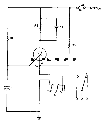
The relay operates for a specific duration, td, after power is applied, followed by an operating time, tc. The SCR activates when the voltage across capacitor Ci reaches a threshold voltage, VA. This action energizes the relay, which remains...
A voltage-to-frequency converter can be constructed using the LM231/331 chip, making it a cost-effective solution for applications such as analog-to-digital conversion and frequency-to-voltage conversion over extended periods. The LM231/331 series of voltage comparators can be effectively utilized to design a...
A function generator that operates within a frequency range of 0.1 Hz to 20 MHz can be constructed using the MAX038 integrated circuit chip. This represents a straightforward implementation of a high-performance signal generator. The MAX038 is a high-speed precision...
This beeper circuit utilizes two 555 integrated circuits (ICs) and can operate within a supply voltage range of 5 to 15V DC. It is suitable for applications requiring an alarm or beeping signal. The first IC (IC1) is configured...
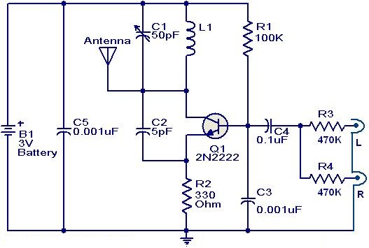
This weblog focuses on electronic circuit schematics, PCB design, DIY kits, and diagrams for electronic projects. The FM transmitter circuit utilizes the NPN transistor 2N2222. The inductor L1 and capacitor C1 generate the necessary oscillations for Q1. The collector...
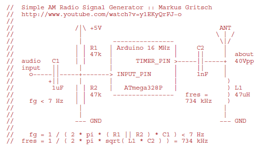
Markus constructed a software AM radio transmitter utilizing an Arduino. The audio signal is supplied to the ADC input via a decoupling capacitor. A PWM output pin directly controls a capacitor-inductor circuit connected to an antenna. The schematic and...