
low power 5 v switching regulator

The low power 5V switching regulator is designed to efficiently convert a higher input voltage to a stable 5V output while minimizing power loss. Switching regulators are preferred in applications where power efficiency is critical, as they utilize a high-frequency switching element to regulate the output voltage, in contrast to linear regulators that dissipate excess voltage as heat.
The circuit typically consists of an input capacitor to filter the input voltage, a switching element (usually a MOSFET), an inductor to store energy, a diode for rectification, and an output capacitor to smooth the output voltage. The control circuitry often includes a feedback loop that monitors the output voltage and adjusts the duty cycle of the switching element to maintain a constant output voltage despite variations in load current or input voltage.
Key specifications for a low power 5V switching regulator include the input voltage range, output current capability, efficiency rating, and switching frequency. These parameters are critical for ensuring the regulator meets the requirements of the specific application, whether it be in battery-powered devices, portable electronics, or other low-power systems.
The circuit diagram associated with this regulator will typically illustrate the connections between these components, showing how the switching element is driven by a control signal, how the inductor and capacitor form a low-pass filter to produce a stable output voltage, and how feedback is implemented to regulate the output effectively. Proper layout and component selection are essential to minimize electromagnetic interference (EMI) and ensure stable operation under varying load conditions.Low Power 5V Switching Regulator power supply. Go to that page to read the explanation about above power supply related circuit diagram. 🔗 External reference
Related Circuits
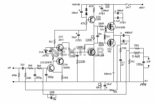
In this circuit we use the 2SK1058 and the 2SJ162 Mosfets. This could be avoided by a fairly simple bootstrapping circuit, but the improvement in maximum output may be just a fraction of a dB, depending on the supply...
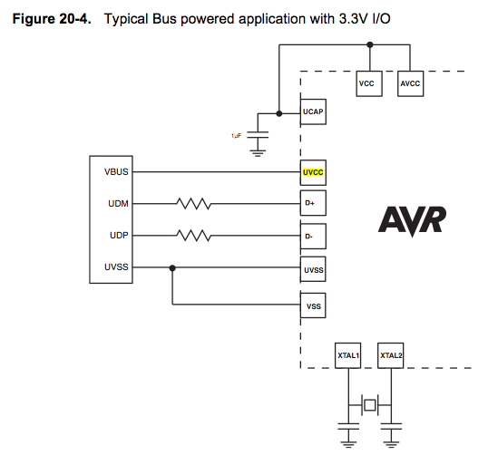
Since the microcontroller unit (MCU) is powered through USB, the common zero voltage should align with the supply voltage and thus be connected to the 0V (UVSS) line. In electronic circuit design, it is essential to ensure that the ground...
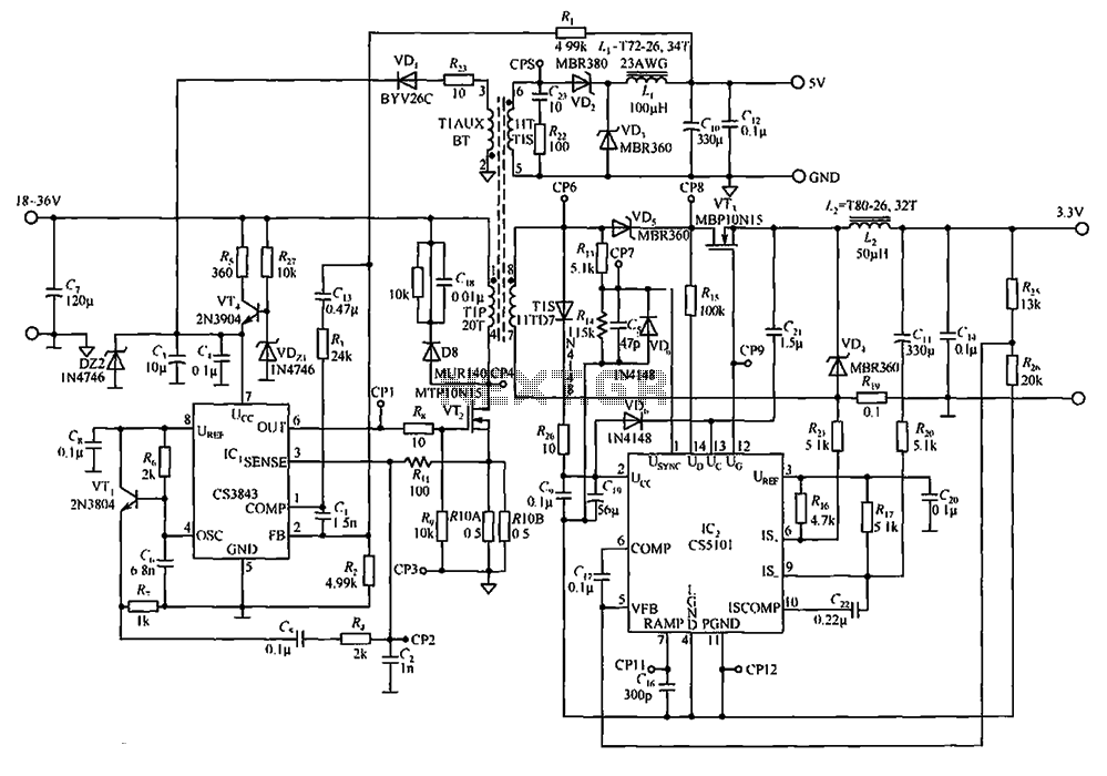
The CS3843 and CS5101 are components of a 5V/3.3V switching DC power supply circuit. The CS3843 is a fixed frequency PWM controller characterized by a set oscillator that precisely controls the duty cycle. It features a temperature-compensated reference voltage,...
The USB charger power supply is designed for use in MP3 and MP4 chargers. It accepts an input of AC 160-240V at 50/60Hz and has a rated output of DC 5V at 250mA. For applications requiring a long-term higher...
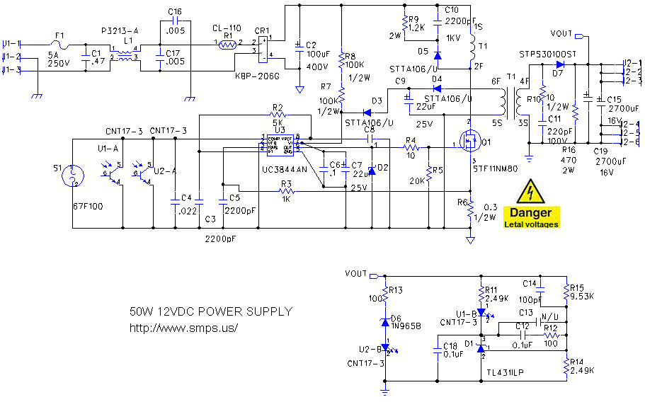
The schematic diagram below illustrates a simple and cost-effective 12-volt DC 50W off-line SMPS (switched-mode power supply) circuit. It is suitable for DIY home projects or for learning about the operation of flyback converters. This power supply unit (PSU)...
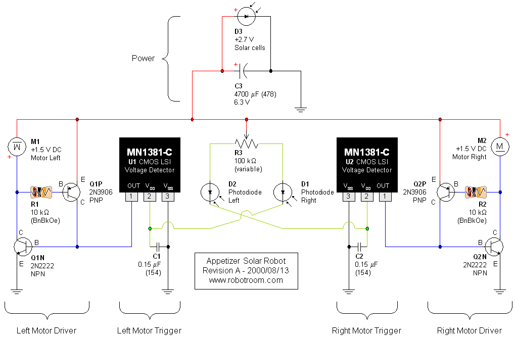
A light-seeking solar-powered tiny robot based on a BEAM design. The article includes pictures, links, a video, and a schematic. The described robot employs a BEAM (Biology, Electronics, Aesthetics, and Mechanics) design philosophy, which emphasizes simple, efficient, and often analog...