
Touch Switches Collection

This one is the equivalent to those banks of push buttons where you push any switch and it releases one already pushed in. I've only shown two stages but you can have 5 - or ten if you wish. Consider the state with the first stage on. Current flows from the 0V line through the 1K resistor, the LED, and the bottom two transistors. The center line will then be at about -10V.
Now touch input 2. The top transistor will pass current into the bottom transistor: the two bottom transistors will turn each other hard and suddenly on. But the 100n capacitor has no voltage across it so it takes a pulse of current as it charges up. Instantaneously the center line drops to -12V and the LED which was on extinguishes. Since the current that was flowing through this LED also flowed through the first pair, these turn off. The first 'button' has been released. Quite a nice, simple circuit for a multi-button touch switch. This is a timer or power switch. Touch the contacts and the switch turns on. After a preset delay, it turns off again. Its output is from a pass transistor so you can use it to operate another circuit during its timeout period. Touching the contacts causes a current to flow through the 4M7 into Tr3's base turning it on. Its collector current turns on Tr2. The 10µ capacitor is not charged, so it charges up, holding Tr3 on. Meanwhile, Tr2's emitter current turns on Tr1, applying power to the load.
While the 10µ is charging (determined by the 4M7 in series with it), the circuit stays on but when the 10µ is sufficiently charged, the current through it is too small to hold on Tr3 and the whole circuit turns off.
You can alter the timing by changing the 4M7 or the 10µ. This is an unusual touch switch that relies on the fact that the voltage drop in a diode is a function of its temperature. Warming the diode up reduces its voltage drop by about 2mV per degree centigrade (at room temperature).
The described touch switch circuit utilizes a combination of capacitive touch sensing and transistor switching to create a user-friendly interface for controlling devices. The operation begins when a user touches the designated area, which generates a small change in capacitance due to the proximity of the human body. This change is detected by the first stage of the circuit, comprised of a resistor and an LED, which indicates the state of the switch.
Once activated, the circuit uses a pair of transistors configured in a feedback loop. The first transistor receives the initial signal, which turns on the second transistor. This action creates a path for current to flow through the LED, illuminating it. The inclusion of a capacitor in the circuit is crucial, as it momentarily stores charge, allowing for a brief delay before the circuit resets, thereby giving the user visual feedback that the switch has been activated.
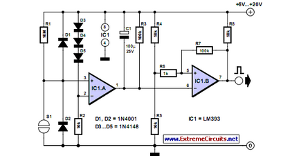
The timing mechanism is adjustable through the use of different resistor (4.7 MΩ) and capacitor (10 µF) values, allowing for customization based on the specific application requirements. The circuit can be used as a timer or power switch, where a touch will turn on the connected load, and after a predetermined delay, the load will turn off automatically.
In addition, the circuit incorporates a temperature-sensitive diode, which introduces an interesting characteristic to the switching behavior. As the diode heats up, its voltage drop decreases, influencing the performance of the circuit based on ambient temperature conditions. This feature can be utilized for applications requiring temperature compensation or for enhancing the sensitivity of the touch switch in varying environmental conditions. Overall, this touch switch circuit demonstrates a practical and innovative approach to user interface design within electronic projects.Touch operated switches are an attractive project for DIY electronics but they are not so common in commercial products. The reason for this is that, although there are many different ways of implementing a touch switch (leakage, hum pickup, capacitance, albedo) all of them rely on body parameters which vary a lot with the person's body, age and environment so that a circuit which gives reliable operation with one development engineer may cause problems in use with, for instance, old folks living in arid areas.
Nevertheless touch switches can give excellent results. This one is the equivalent to those banks of push buttons where you push any switch and it releases one already pushed in. I've only shown two stages but you can have 5 - or ten if you wish. Consider the state with the first stage on. Current flows from the 0v line through the 1K resistor, the LED and the bottom two transistors. The centre line will then be at about -10v. Now touch input 2. The top transistor will pass current into the bottom transistor: the two bottom transistors will turn each other hard and suddenly on.
But the 100n capacitor has no voltage across it so it takes a pulse of current as it charges up. Instantaneously he centre line drops to -12v and the LED which was on extinguishes. Since the current that was flowing through this LED also flowed through the first pair, these turn off. The first 'button' has been released. Quite a nice, simple circuit for a multi button touch switch. This is a timer or power switch. Touch the contacts and the switch turns on. After a preset delay it turns off again. Its output is from a pass transistor so you can use it to operate another circuit during its timeout period.
Touching the contacts causes a current to flow through the 4M7 into Tr3's base turning it on. Its collector current turns on Tr2. The 10µ capacitor is not charged, so it charges up, holding Tr3 on. Meanwhile Tr2's emitter current turns on Tr1, applying power to the load. While the 10µ is charging (determined by the 4M7 in series with it) the circuit stays on but when the 10µ is sufficiently charged the current through it is too small to hold on Tr3 and the whole circuit turns off. You can alter the timing by changing the 4M7 or the 10µ. This is an unusual touch switch that relies on the fact that the voltage drop in a diode is a function of its temperature.
Warming the diode up reduces its voltage drop by about 2mV per degree centigrade (at room temperature). 🔗 External reference
Related Circuits
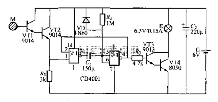
A two-battery powered light touch delay circuit designed for convenience at night. It can be placed on a bed pillow, and when the metal contact M under the capsule is touched, a small lamp will automatically light up. The...
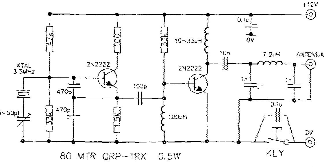
A Morse key is essentially an electrical switch that can define two states: on and off. Despite its simplicity, there is significant potential for artistry, and many Morse keys are considered works of art. The collection includes keys that...
Mechanical contacts have the disadvantage that they wear out. That is why it is practical to use an electronic touch switch in some situations. The electronic touch switch serves as an effective alternative to mechanical contacts, addressing the issue of...
This electronic circuit utilizes a 555 timer as the foundation for a touch switch. When the plate is touched, the 555 timer is activated, causing the output on pin 3 to go high, which turns on the LED and...
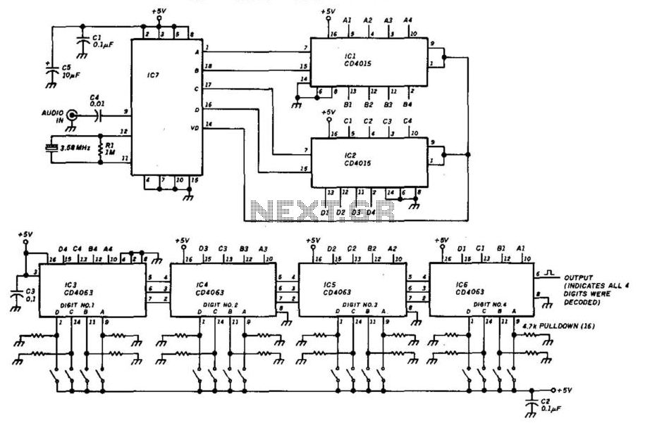
This decoder will respond to a preselected 4-digit DTMF number. IC7 is a Radio Shack IC device (part #276-1303). The logic is all CMOS. The digits are selected by SW1 and SW2, a pair of 8-position DIP switches. The described...
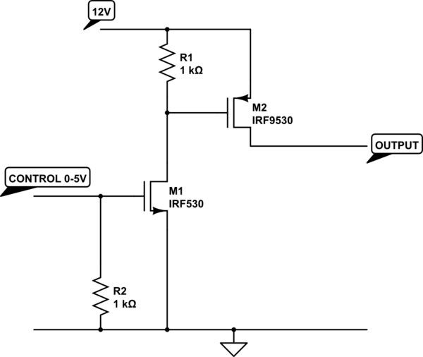
The transistor depicted is a P-channel MOSFET functioning as a high-side switch. Typically, an N-channel MOSFET is preferred for low-side switching, but the P-channel variant can be utilized effectively with the addition of a load at the drain. When...