
Touch Switch Circuit with explnation
The described electronic circuit is a touch-activated switch based on the 555 timer IC, a versatile component widely used in timer, delay, pulse generation, and oscillator applications. The 555 timer operates in monostable mode in this configuration, where it generates a single output pulse when triggered.
In this circuit, the touch plate acts as a trigger mechanism. When the plate is touched, it sends a signal to pin 2 of the 555 timer, which is configured to respond to a negative-going edge. The 10M resistor connected to pin 2 ensures high sensitivity, allowing the circuit to detect even slight touches. This high-resistance value minimizes the current draw and enhances the responsiveness of the switch.
The timing component of the circuit is determined by the resistor and capacitor connected to pins 6 and 7. The time period for which the output remains high (i.e., the duration that the LED and buzzer are activated) can be calculated using the formula:
\[ T = 1.1 \times R \times C \]
where \( T \) is the time in seconds, \( R \) is the resistance in ohms, and \( C \) is the capacitance in farads. By selecting appropriate values for the resistor and capacitor, the user can customize the duration of the output pulse to suit specific requirements.
The output on pin 3 of the 555 timer is capable of driving an LED directly, providing visual feedback when activated. Additionally, the output can be connected to a buzzer, which produces an audible signal, enhancing the functionality of the touch switch.
Overall, this circuit exemplifies the practical application of the 555 timer in creating a simple yet effective touch-sensitive switch, suitable for various electronic projects and educational purposes.This electronic circuit uses a 555 timer as the bases of the touch switch. You can learn more about 555 timers in the Learning section on my site. When the plate is touched the 555 timer is triggered and the output on pin 3 goes high turning on the LED and the buzzer for a certain period of time. The time that the LED and the buzzer is on is based on the values of the capacitor and resistor connected to pin 6 & 7. The 10M resistor on pin 2 causes the the circuit to be very sensitive to the touch. Disclaimer All files are found using legitimate search engine techniques. This site does not and will not condone hacking into sites to create the links it list. We will and do assume that all links found on the search engines we use are obtained in a legal manner and the webmasters are aware of the links listed on the search engines. If you find a URL that belongs to you, and you did not realize that it was "open to the public", please use the report button to notify the blogmaster of your request to remove it or it will remove within 24 hours.
This is not an invitation for webblog haters to spam with requests to remove content they feel that is objectionable and or unacceptable. Proof of URL ownership is required. NOTICE: This Blog Has Already Been Reviewed And Accepted By Blogger. com 🔗 External reference
Related Circuits
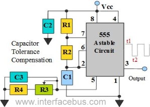
The 555 Timer is configured as an astable multivibrator. Additional components have been incorporated to enhance circuit operation. Upon powering the circuit, the 555 Timer will generate a square wave, determined by the values of Capacitor C1 and Resistors...
The current feedback operational amplifier maintains a consistent bandwidth even when the open-loop gain is altered. This characteristic makes it particularly suitable for applications in video signal amplification and the driving circuits of video cables. The accompanying diagram illustrates...

This circuit was first introduced by Signetics Corporation as the SE555/NE555 around 1971. Pin connections and functions are as follows: Pin 1 (Ground) is the most negative supply potential of the device, typically connected to circuit common when powered...
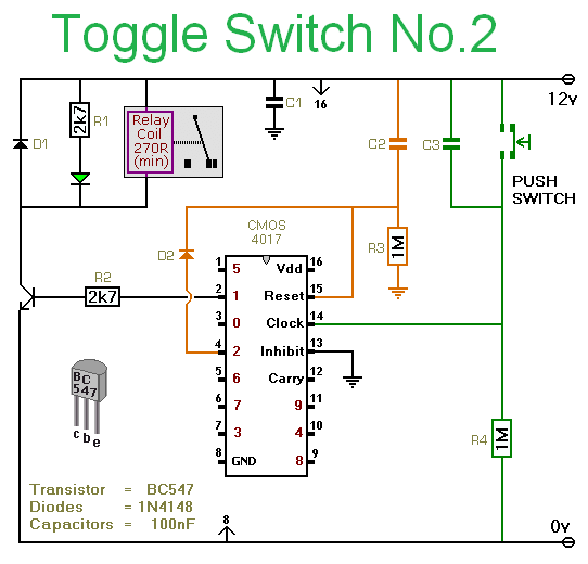
This circuit utilizes a CMOS 4017 decade counter, which begins counting from zero and advances by one each time pin 14 is activated. Upon reaching nine, the count resets to zero and starts over. As the count progresses, each...
This circuit is a sound generator designed to create a super siren alarm signal using a live frequency generator circuit that incorporates an operational amplifier (op-amp). The circuit operates on the principle that when switch S1 is not pressed,...
This circuit allows the use of an inexpensive loudspeaker as a microphone. Sound waves that reach the speaker cone cause fluctuations in the voice coil. The movement of the voice coil within the speaker's magnetic field generates a small...