
Toy Car Remote Control
The circuit design can be broken down into two primary sections: the transmitter and the receiver. The transmitter section is composed of the two astable multivibrators which generate the necessary frequencies for communication. The first multivibrator (T1 and T2) produces a low-frequency signal that can modulate the IR beam, while the second multivibrator (T3 and T4) operates at a higher frequency (38 kHz) suitable for IR transmission. This frequency is essential for minimizing interference from ambient light sources, enhancing the reliability of the IR communication.
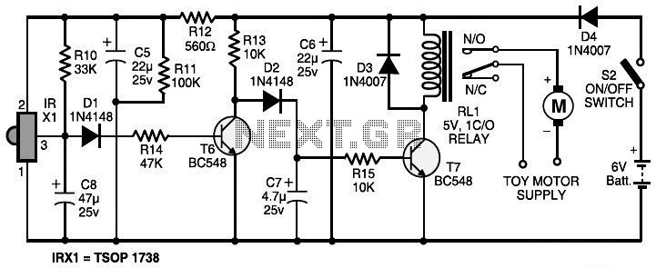
The IR LED (LED1) serves as the primary transmitter of the modulated signal, emitting infrared light that carries the encoded commands to the receiver. The receiver circuit, centered around the TSOP1738, is designed to be sensitive to the specific frequency of the transmitted signal. When the TSOP1738 detects the IR signal, it outputs a low signal, which is then processed by the following transistor stages.
Transistor T6 acts as a switch, controlling whether the signal can proceed to the relay driver T7. If T6 is turned off (when the IR signal is received), T7 is enabled, allowing current to flow through the relay coil (RL1), thus activating the toy car. The use of diode D1 protects the circuit from back EMF generated when the relay coil is de-energized, ensuring the longevity and reliability of the components.
Overall, this circuit provides a straightforward method for controlling a toy car via infrared signals, with potential for further enhancements to allow for more complex movements such as turning or speed adjustments.The circuit, consisting of an infrared transmitter-receiver pair, utilizes IR beam transmission to switch the toy car on` or off, yeah it will be only switching on and switching off, you may modify this circuit to make the toy car t The circuit, consisting of an infrared transmitter-receiver pair, utilizes IR beam transmission to switch th e toy car on` or off`, yeah it will be only switching on and switching off, you may modify this circuit to make the toy car to turn left or right. To operate the toy car, you have to hold the transmitter in your hand, trying to keep it pointed at the toy car which has the receiver fitted inside, and just simply press a switch assigned on the transmitter.
The transmitter operates off 9V DC supply, while the receiver will require only 6V DC supply. The transmitter circuit is constructed around two BC558 transistors (T1 and T2), 3 BC548 transistors (T3, T4 and T5), IR LED1 and a several discrete components. In the transmitter circuit, you will find two astable multivibrators. The first, designed around transistors T1 and T2, generates a frequency of about 1. 2 kHz. The 2nd, designed around transistors T3 and T4, generates about 38 kHz. IR LED1 is utilized to transmit the 38kHz frequency. In the receiver circuit, TSOP1738 receives the IR signal transmitted by IR LED1 of the transmitter circuit.
The output of TSOP1738 is fed to transistor T6 through diode D1. The amplified signal is further provided to relay-driver transistor T7. Relay RL1 energises to control the toy car. Working of the receiver circuit is very simple. At first, when no IR beam is falling on sensor TSOP1738, the relay stays de-energised and the toy car does not move. When switch S1 is pressed, the IR beam falls on TSOP1738 and its output goes low. Transistor T6 cuts off and transistor T7 conducts to energise relay RL1 and move the toy car. 🔗 External reference
Related Circuits
These units can be useful as a short-range, single-channel remote-control. When the pushbutton in the transmitter circuit is briefly activated, the LED D1 in the receiver illuminates and an optional beeper or relay can be operated. Circuit operation is...
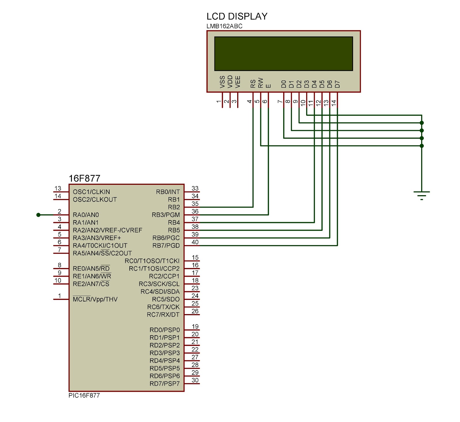
This document outlines the connection of a 16x2 LCD display to a microcontroller, specifically the PIC 16F877A. The circuit diagram is provided, although power supply and oscillator connections for both the PIC and LCD are not depicted. The LCD...
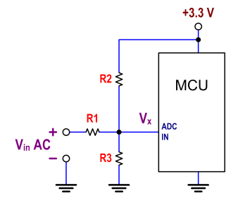
The ATtiny24 microcontroller's ADC is utilized to record an AC signal, which operates within a voltage range of 0 to 3.3V. A precision rectifier is employed to eliminate the negative portion of the signal. The circuit incorporates an LMC6484...
This AC motor speed controller can handle most universal type (brushed) AC motors and other loads up to about 250W. It works in much the same way as a light dimmer circuit; by chopping part of the AC waveform...
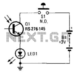
Using a battery, a phototransistor, and a visible-light LED, this simple circuit functions as a "go/no go" tester for infrared remote control devices. The illumination of the LED indicates that the phototransistor is being modulated by infrared energy. This circuit...

The battery should charge up to 14 volts. A reading of 10.7 volts indicates that one cell is shorted. A good way to diagnose this further is to look at the water level in the cells. The shorted cell...