
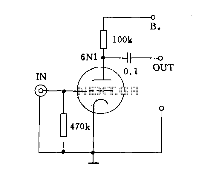
Tube amplifier input voltage input
In audio systems, the input impedance plays a critical role in determining the compatibility between different components. High-impedance inputs are designed to connect with sources that have a high output impedance, ensuring minimal loading on the source device. This is especially important in audio applications, where maintaining signal integrity is crucial for optimal performance.
For instance, devices like CD players and tuners often utilize high-impedance inputs to interface with microphones or other audio sources, which may have varying output impedances. The high input impedance allows these devices to receive signals without significantly affecting the source's performance, preserving audio quality and dynamic range.
Conversely, low-impedance inputs are typically used in applications where the input device can drive the load effectively, such as in professional audio equipment or mixing consoles. These inputs are designed to handle lower output impedances, ensuring that the audio signal is transmitted efficiently without distortion.
In summary, understanding the distinction between high-impedance and low-impedance inputs is essential for designing audio systems that meet the specific requirements of various devices, ensuring optimal performance and sound quality across the entire audio chain.Depending on the input impedance can be divided into a high-impedance input and low impedance input in two ways. Its major input in various audio equipment to the requirements of the load impedance to decide.High impedance input mode: As a general audio equipment such as CD, VCD, DVD, recording deck, tuner input voltage amplifier.
Related Circuits
In this circuit, an LM339 quad voltage comparator is utilized to generate a time delay and control a high current output at low voltage. Approximately 5 amps of current can be sourced using a pair of fresh alkaline D...
I built this headphone amplifier for dynamic headphones based on my rules of proper audio design. People who know my designs will realize that this amplifier is much more than just a headphone amp. It is a pure class...
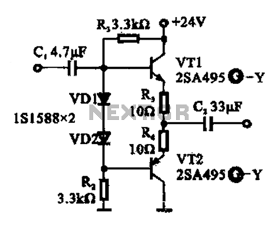
A buffer amplifier is utilized as a transistor emitter follower buffer amplifier for applications that necessitate a high input impedance. The circuit employs a complementary push-pull configuration. The signal input is connected to the base of transistor VT1, which...
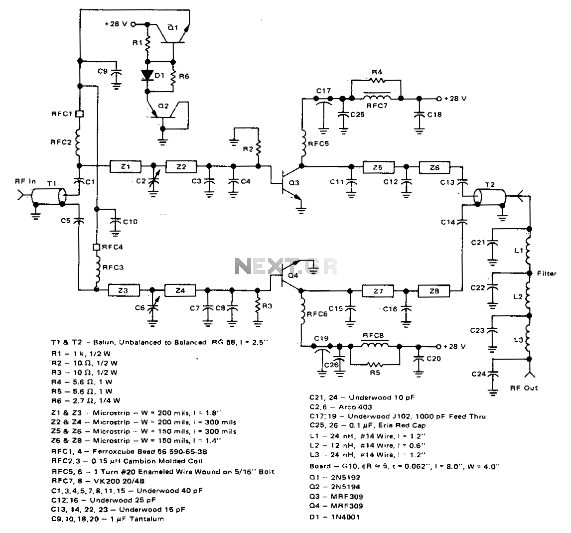
This 100-watt linear amplifier can be built using two MRF309 transistors in a push-pull configuration, requiring only 16 watts of drive power within the frequency range of 420 to 450 MHz. It operates from a 28-volt supply and achieves...
That circuit protects the overdriven signals going into an amplifier. Instead of a zener diode, we use a transistor. That way we ensure that the above the ordinary input voltages (1 volt r.m.s.) can be achieved without distortion. Also,...
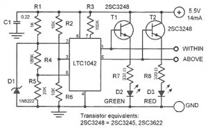
This device is designed to control a supply voltage of +5 V. It provides information signals at TTL levels, accompanied by an LED display that indicates whether the voltage is within the nominal value or deviates from it. The...
Warning: include(partials/cookie-banner.php): Failed to open stream: Permission denied in /var/www/html/nextgr/view-circuit.php on line 713
Warning: include(): Failed opening 'partials/cookie-banner.php' for inclusion (include_path='.:/usr/share/php') in /var/www/html/nextgr/view-circuit.php on line 713