
Electronic Muscle Stimulator Circuit
The electronic muscle stimulator circuit operates by delivering electrical impulses through electrodes placed on the skin. These impulses mimic the natural signals sent by the nervous system to stimulate muscle contractions. The circuit typically consists of a microcontroller, which generates the desired pulse patterns, a power supply to provide the necessary voltage, and a driver circuit to amplify the signals before they reach the electrodes.
Key components of the circuit include:
1. **Microcontroller**: This component is programmed to control the timing, frequency, and duration of the electrical impulses. It allows for customization of the stimulation patterns based on user needs.
2. **Power Supply**: A stable power source is essential for the operation of the circuit. This could be a battery or an AC-to-DC converter, depending on the design. The power supply must provide sufficient voltage and current to drive the electrodes effectively.
3. **Driver Circuit**: This section amplifies the signals generated by the microcontroller. It may include transistors or operational amplifiers to ensure that the output signals are strong enough to stimulate the muscles.
4. **Electrodes**: These are placed on the skin and are the interface between the circuit and the body. They can be adhesive pads or other types designed to ensure good contact with the skin for effective stimulation.
5. **Control Interface**: A user-friendly interface, which may include buttons or a touchscreen, allows the user to select different modes of stimulation, adjust intensity levels, and set timers for treatment sessions.
6. **Safety Features**: To ensure safe operation, the circuit may include features such as current limiting, automatic shutoff after a certain period, and isolation between the user and the electrical components.
This electronic muscle stimulator circuit is beneficial for various applications, including physical therapy, rehabilitation, and pain management, providing a non-invasive method to enhance muscle function and alleviate discomfort.This is an electronic muscle stimulator circuit that stimulates nerves of that part of your body where electrodes are attached. It is useful to relieve hea.. 🔗 External reference
Related Circuits
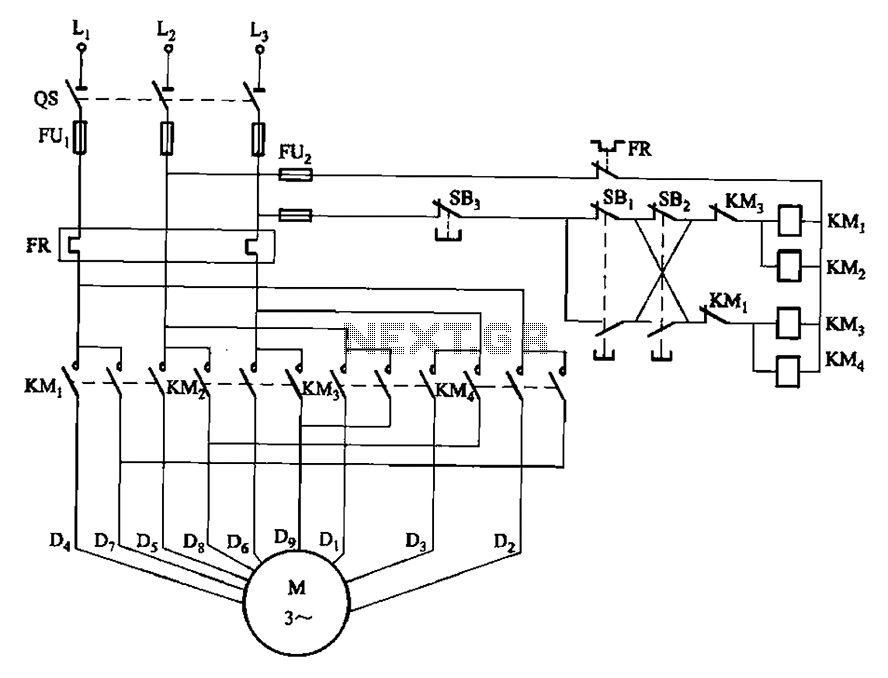
The circuit depicted in Figure 3-112 features two operation buttons: SBi, which serves as the first speed operation button, and SBz, which operates the second speed class. Both buttons facilitate two speeds in the same direction. The circuit design incorporates...
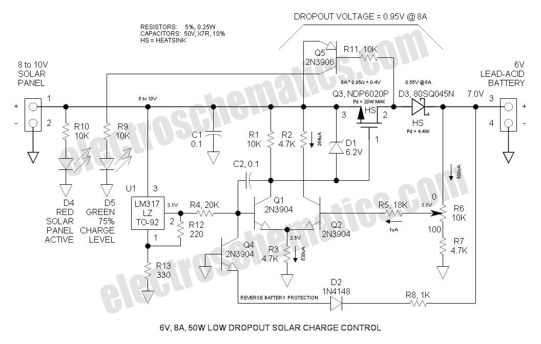
This Low Dropout Voltage (LDO) solar charge controller utilizes a straightforward differential amplifier combined with a series P-channel MOSFET linear regulator, ensuring compatibility and efficiency in solar energy applications. The Low Dropout Voltage (LDO) solar charge controller is designed to...
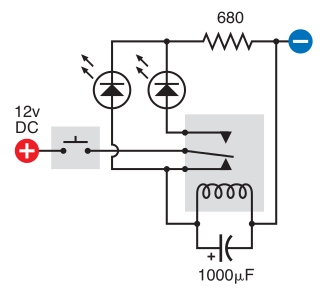
The intended result is for the relay to oscillate and the LEDs to flash when the button is pressed. However, when the button is pressed, the leftmost LED lights constantly, and nothing else happens. There is voltage across the...
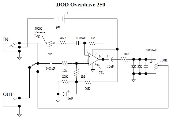
This document provides a circuit diagram for the DOD Overdrive 250 preamp. The DOD Overdrive 250 is similar to the MXR Distortion Plus and several other devices, utilizing a 741 operational amplifier with two diodes on the output channel....
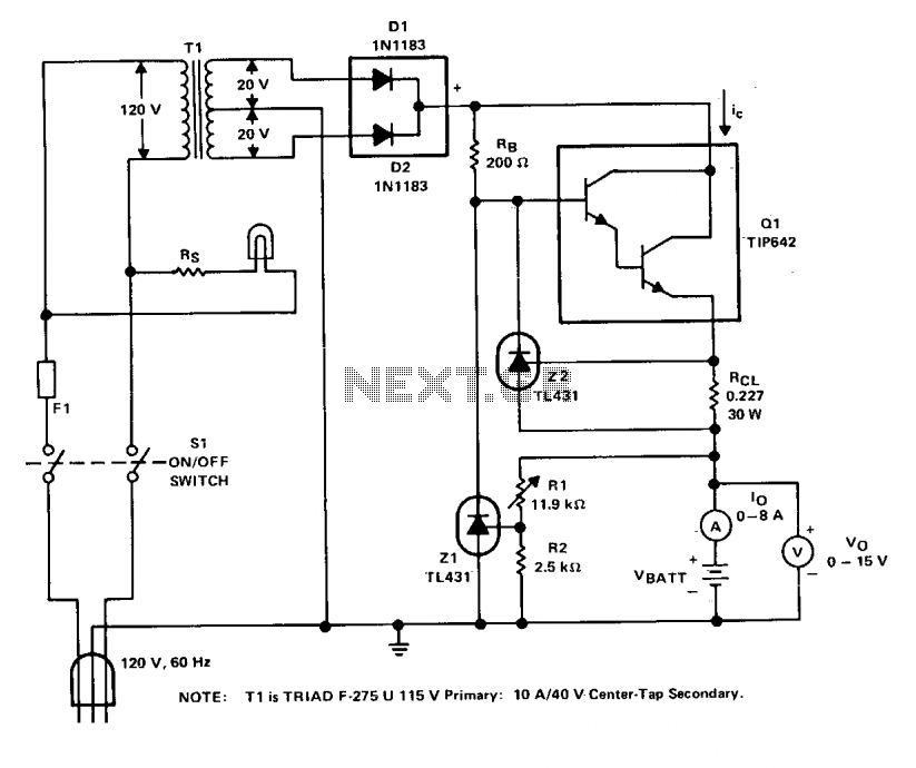
The charger operates with a charging voltage of 2.4 V per cell, aligning with the recommendations of most manufacturers. The circuit delivers a charging voltage of 14.4 V (6 cells at 2.4 V per cell) in a pulsed manner...
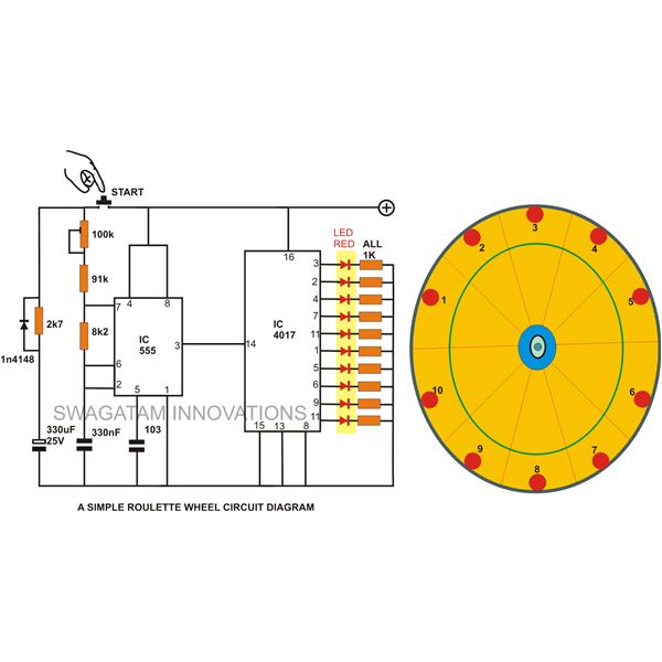
A simple circuit for a 10 LED roulette wheel is presented. Pressing the button initiates the LEDs in a rotational sequence that starts at full speed and gradually decelerates until it halts at a randomly selected LED. The randomness...