
Transformer AC contactor DC operation circuit b
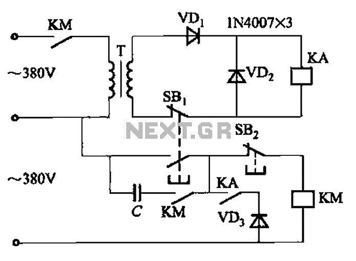
The AC contactor DC transformer circuit is designed to control and manage electrical power in applications where alternating current (AC) is converted to direct current (DC). This circuit typically involves the use of a transformer that steps down or steps up the voltage level of the AC supply, followed by an AC contactor that acts as a switch to control the power flow.
In this configuration, the transformer is crucial for isolating the AC supply from the DC load while ensuring that the voltage is appropriately adjusted for safe operation. The AC contactor, which is an electromechanical switch, is utilized to turn the circuit on or off based on control signals, providing a reliable means to manage high-power loads.
The design of this circuit includes several key components: the transformer, the AC contactor, rectifiers for converting AC to DC, and protection devices such as fuses or circuit breakers to prevent overloads. The rectification process is typically achieved through a diode bridge, which allows current to flow in one direction, thus converting the AC signal into a usable DC voltage.
This type of circuit is commonly used in industrial applications, automation systems, and various electronic devices where DC power is required but sourced from an AC supply. Proper selection of components and careful consideration of the circuit layout are essential to ensure efficiency, reliability, and safety in operation.AC contactor DC transformer circuit has run a variety of types, Transformer AC contactor DC operation circuit b
Related Circuits

This circuit delivers an initial voltage of 2.5V per cell to rapidly charge a car battery. The charging current decreases as the battery charges. This circuit is designed to provide an efficient charging solution for car batteries by applying an...
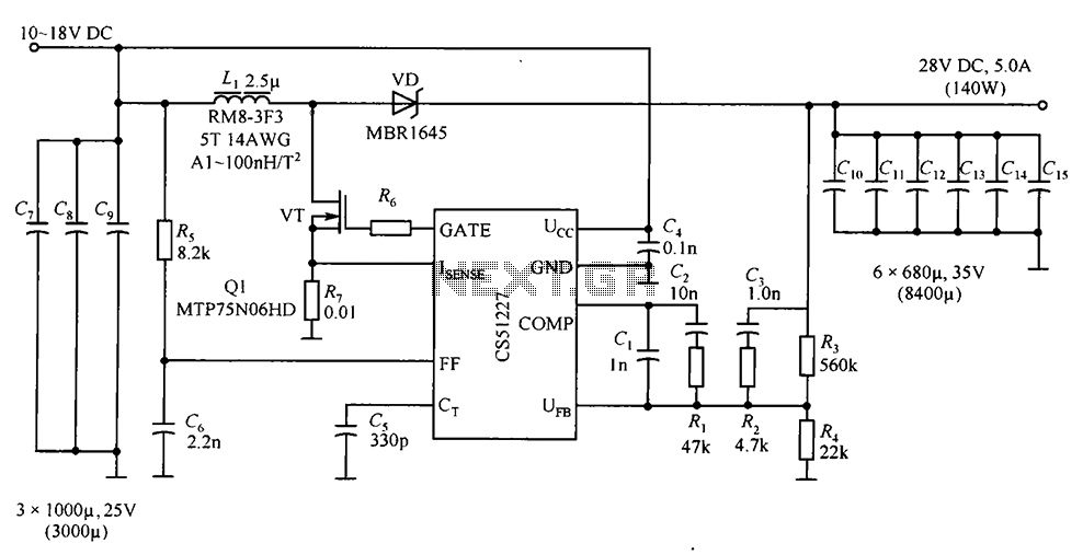
CS51227 is a voltage-type PWM controller that delivers an output of 28V with a maximum current of 5A. The switching frequency is 1.0 MHz, with a starting voltage of 4.7V and a starting current of 75A. The input voltage...
There have been numerous inquiries regarding this project, primarily due to issues with the source code provided at the end of the author's notes. This problem has been widely reported online, and similar compilation errors have been encountered. It...

This design outlines a door alarm circuit that utilizes an electronic system. It features a synthesized sound chip from Holtek, specifically the HT-2811, which reproduces the sound of a "ding-dong" chiming doorbell. The circuit also incorporates a CMOS 4026...

This circuit is designed as a 10-channel LED sequencer with the addition of solid-state relays for controlling AC lamps. The circuit operates using relays. The relay depicted in the diagram is a Radio Shack 3 amp unit (part no....
This design outlines a phone bug circuit. The wireless telephone line spy circuit is capable of transmitting phone conversations to a nearby FM radio. The circuit must be connected to a standard phone line. In the circuit, the first...
Warning: include(partials/cookie-banner.php): Failed to open stream: Permission denied in /var/www/html/nextgr/view-circuit.php on line 713
Warning: include(): Failed opening 'partials/cookie-banner.php' for inclusion (include_path='.:/usr/share/php') in /var/www/html/nextgr/view-circuit.php on line 713