
Transformerless Power Supply
The described circuit operates as a capacitive power supply, which is an efficient method to provide a stable voltage output with minimal heat generation. By leveraging capacitive reactance, the circuit can limit current flow without the energy loss typically associated with resistive components.
In this design, a capacitor is connected in series with the load, allowing it to charge and discharge, thereby supplying the required current. The value of the capacitor determines the reactance and, consequently, the current output. For a 12-volt output, the capacitor must be selected based on the desired current (20 mA) and the frequency of the AC source, as the capacitive reactance (Xc) is given by the formula:
Xc = 1 / (2πfC)
where:
- Xc is the capacitive reactance in ohms,
- f is the frequency in hertz,
- C is the capacitance in farads.
To ensure the circuit can handle the required current without overheating, appropriate voltage ratings for the capacitor must be selected, typically exceeding the maximum expected voltage. Additionally, it is crucial to implement safety features such as fuses or circuit breakers to prevent overcurrent situations.
The output voltage can be smoothed using a rectifier circuit if a DC output is desired, followed by filtering capacitors to reduce ripple. This setup allows the circuit to maintain a stable output voltage while efficiently supplying the necessary current to the load.
Overall, this capacitive power supply circuit is ideal for applications where low power consumption and minimal heat generation are critical, such as in LED lighting or low-power electronic devices.This circuit will supply up to about 20ma at 12 volts. It uses capacitive reactance instead of resistance; and it doesn t generate very much heat.The circ.. 🔗 External reference
Related Circuits
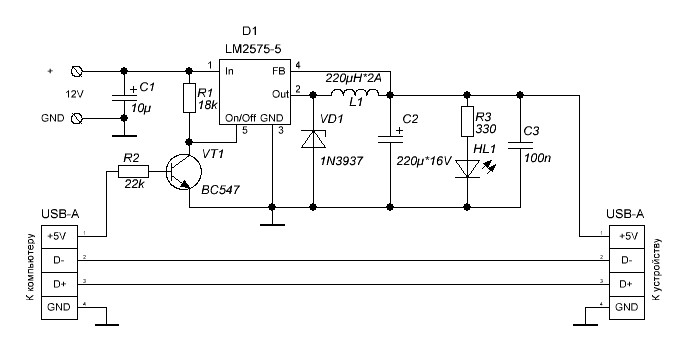
Additional power supply for USB devices. Refer to the page for an explanation of the related circuit diagram. The additional power supply for USB devices is designed to enhance the power availability for devices that may require more current than...

This is a design circuit diagram of a moderate power FM transmitter circuit. The circuit operates using two transistors. It consists of a complete circuit diagram. The operation of this circuit is explained as follows: the voice signals picked...
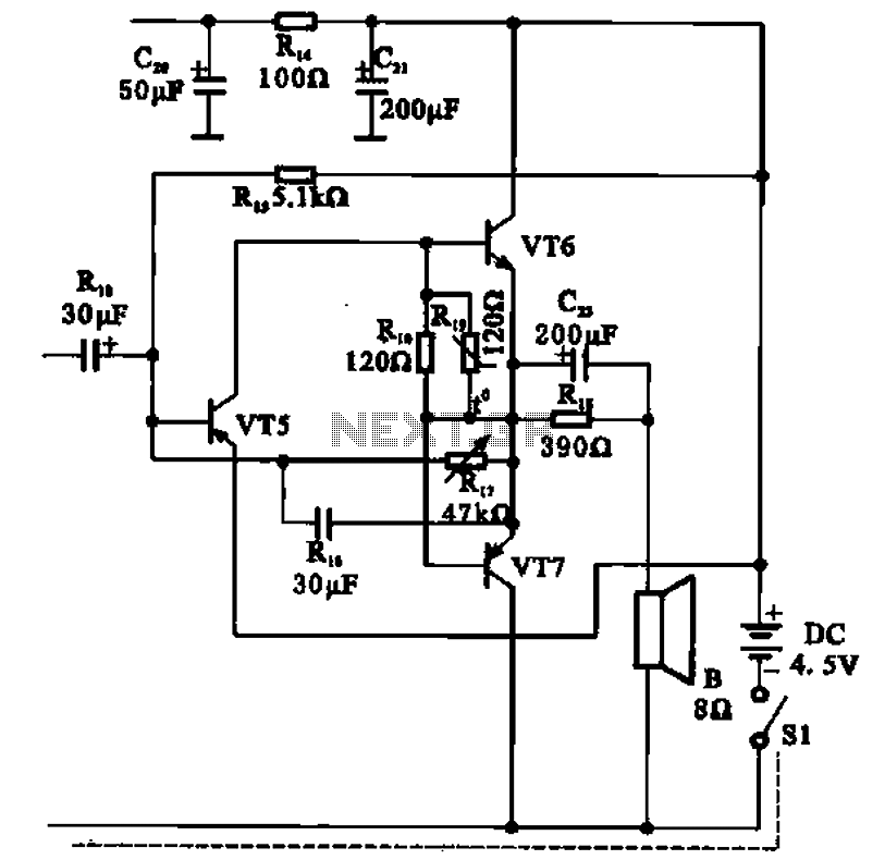
The transistor radio features a common output transformerless (OTL) power amplifier circuit. The VT5 component serves as the bias resistor for the driver stage. VT6 and VT7 form a complementary symmetry configuration, with VT6 being a germanium NPN transistor...
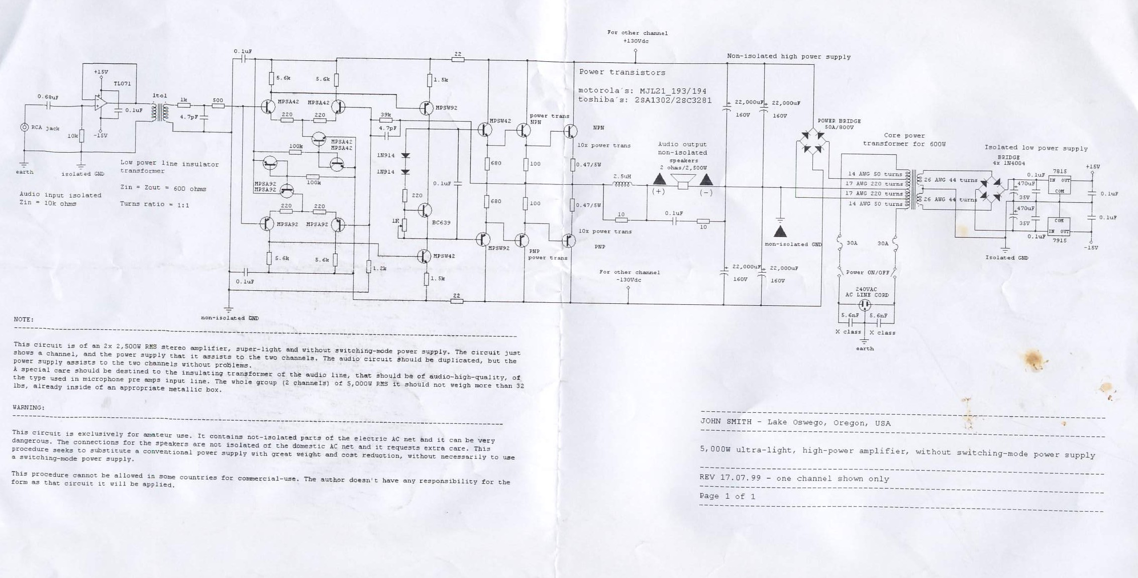
This circuit is for a 2x2, 500W RMS stereo amplifier that is super-light and does not utilize a switching-mode power supply. The circuit diagram displays only one channel, while the power supply is designed to support both channels. The...
The fixed voltage power supply is useful in applications where an adjustable output is not required. This supply is simple, but very flexible as the voltage it outputs is dependent only on the regulator and transformer you choose. The...
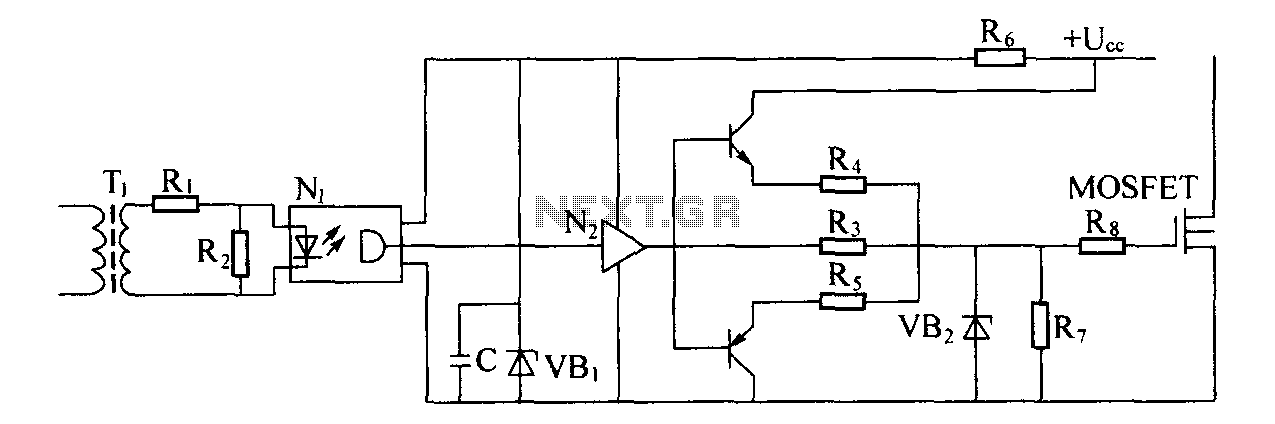
Driver circuit diagram: The primary function of the driver circuit is to serve as a variable width pulse width modulator output power amplifier, providing a drive signal to high voltage power switching devices. The driving circuit typically plays a...