
transistor astable multivibrator
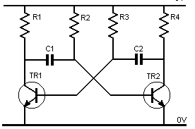
The described circuit operates as an astable multivibrator, a fundamental configuration used for generating square wave signals. The circuit comprises three transistors (TR1, TR2, and TR3), two capacitors (C1 and C2), and a resistor (R1).
Initially, when TR1 is turned on, it allows current to flow from the collector to the emitter, creating a low voltage across its collector-emitter junction. This condition allows capacitor C1 to charge, which in turn affects the base voltage of TR2. As the voltage across C2 rises, it eventually reaches the threshold of 0.6 volts, turning on TR2. This transition is critical, as it creates a feedback loop that influences the state of TR1.
The interaction between TR1 and TR2 is key to the operation of the astable multivibrator. When TR2 turns on, it pulls the collector voltage low, which is fed back to TR1, causing it to turn off. This action leads to an increase in the collector voltage of TR1, which is coupled back to TR2, ensuring that it remains in a conductive state. The charging of capacitor C2 continues until the base voltage of TR1 rises again, completing the cycle.
The timing of the oscillation is determined by the values of the capacitors and the resistor. The discharge and charge times of the capacitors dictate the frequency of the output waveform. The circuit can be used in various applications, including clock generation, tone generation, and as a flip-flop in digital circuits. The astable multivibrator's ability to produce a continuous square wave makes it a versatile building block in electronic design.Assume one of the transistor, say TR1 become conducting at first. Now, since TR1 is conducting, it`s collector emiter voltage should be ideally zero, but any way, it will be around 0. 1 volt and it`s base emiter voltage is +0. 6v. Now the capacitor c1 will start charging. When the base voltage of TR2 become +. 6 due to the increase in the c2 voltage, the transistor TR2 starts conducting. At this moment, voltage at TR2 collector becomes low. The low voltage (<. 6) is coupled to TR2 base and this makes the TR1 to become non conducting. Now when TR1 become non conducting, the collector voltage of TR1 become high due to the resistor R1 and this is coupled to base of TR2 to make it perfectly conducting state. Thus now TR2 become conducting and TR1 become non conducting. Now since TR2 become conducting, c2 starts to charge and thus the base voltage of TR1 is gradually increasing.
Now, when it reaches >0. 6v, TR1 becomes conducting and this reduces the voltage across TR1 collector and this low voltage is coupled to base of TR3 via capacitor c1 which makes TR2 nonconducting. Now the high voltage from TR2 collector is coupled to TR1 base via capacitor c2 which makes the TR1 completly conducting.
Now the above process repeats and thus the transistor become ON OFF alternatively. Thus it is called as an astable multvibrator. 🔗 External reference
Related Circuits
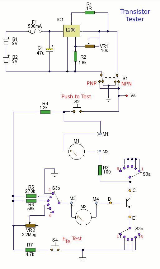
Using the tester is straightforward. Begin with the power off and insert a transistor into the test socket. Set switch S1 for either NPN or PNP configuration and rotate switch S3 to the desired test position. Adjust variable resistor...
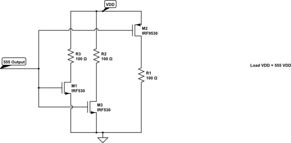
A variable frequency, variably duty cycle 555 configuration is set up in astable mode. A set of potentiometers is utilized to achieve a wide range of control. The output is functioning well; however, there is an issue. The circuit...
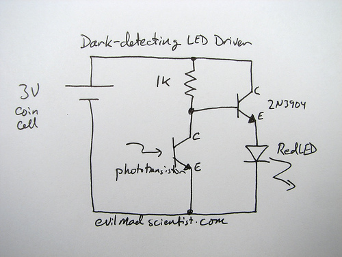
The following circuit illustrates a simple and inexpensive dark-detecting LED circuit. Features include the use of photoresistors, specifically a photocell or LDR, and an LED. This circuit utilizes a light-dependent resistor (LDR) as the primary sensing element. The LDR exhibits...
The bipolar junction transistor is one of the cornerstones of modern solid-state electronics. Understanding the basics of this important active device is essential. The Bipolar Junction Transistor (BJT) initiated the revolution in solid-state electronics during the 1960s. Although discrete...
This circuit is similar to the previous one but employs positive feedback to enhance the amplitude delivered to the speaker. It was adapted from a small five-transistor radio that utilizes a 25-ohm speaker. In the prior circuit, the load...
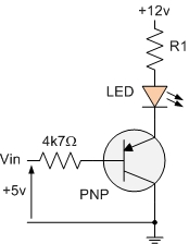
The PNP transistor is the exact opposite of the NPN transistor discussed in the previous tutorial. In this type of transistor construction, the two diodes are reversed compared to the NPN type, resulting in a Positive-Negative-Positive configuration, with the...