
transistor circuit diagram
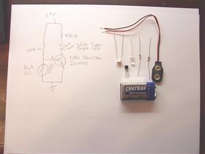
No description available.
Related Circuits
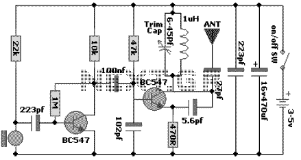
The following schematic diagram shows the design of a 100 MHz Radio Frequency RF Oscillator Circuit. The electrets microphone picks up and amplifies sound then fed it into the audio amplifier stage built around the first transistor. The output...
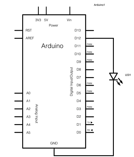
The schematic for this project consists of adding a single 5mm LED to one digital output port on the Arduino. The main components in the schematic include the Arduino Uno, a 5mm LED, and a USB cable. The left...
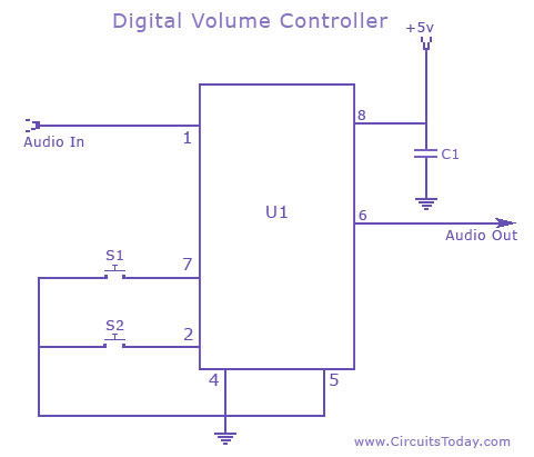
A digital volume control circuit diagram utilizing the DS1669, a potentiometer integrated circuit. This circuit can serve as a digital volume controller for audio amplifiers and various other applications. The digital volume control circuit employs the DS1669 integrated circuit, which...
This inverter is designed to operate appliances such as TVs and stereos while traveling or camping. It converts 12 VDC to 120 VAC, with the output wattage determined by the transistors used for Q1 and Q2, as well as...
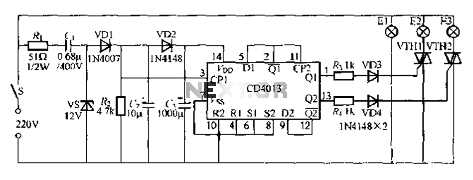
Figure 296 illustrates a control circuit that utilizes a switch (S) to manage three lamps (E1, E2, and E3) in a lighting system, suitable for controlling a chandelier in a living room. When the switch is off, all lights...
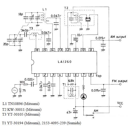
A very simple FM IF MW radio receiver circuit can be designed using the LA1260 IC manufactured by Sanyo Semiconductor. This FM IF MW radio receiver circuit schematic shows that the LA1260 IC can be utilized in AM and...