
1 Transistor Toggle Relay schematic
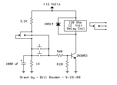
The circuit has three distinct advantages: it requires only a few parts, always comes up with the relay deactivated, and doesn't need any switch debouncing. However, since the capacitor will begin charging as soon as the button is depressed, the button cannot remain depressed too long to avoid re-engaging the relay. This problem can be minimized with an additional resistor connected from the transistor base to ground so that the base voltage is close to 0.7 volts with the button depressed and the transistor is biased in the linear region. With the button held down, the relay coil voltage should be somewhere between the pull-in and drop-out voltages so that the relay will maintain the last toggled state. This worked out to about 820 ohms for the circuit built using a 12-volt, 120-ohm relay coil and 2N3053 transistor. Temperature changes will affect the situation, but the operation is still greatly improved. Heating the transistor with a hair dryer found that the relay will re-engage with the button held down for approximately 1 second, but this is not much of a problem under normal operation.
The circuit utilizes a double pole, double throw (DPDT) relay, which allows for versatile control over the load and feedback mechanisms. The momentary push button serves as the primary input for toggling the relay state. Upon pressing the button, the capacitor begins to charge, and the voltage across it is fed to the base of the transistor through a 560-ohm resistor. This configuration ensures that the transistor operates in saturation, allowing sufficient current to flow through the relay coil, thus activating the relay.
In the active state, the relay contacts are configured to provide a feedback loop that maintains the transistor in the on state. The combination of a 3.3K resistor and a 560-ohm resistor connected to the base of the transistor ensures a stable operating point, allowing the relay to remain engaged until the momentary push button is released. The capacitor discharges through a 1K resistor, which assists in controlling the timing of the relay's disengagement.
The design's simplicity is a notable advantage, as it minimizes component count while maintaining reliable operation. The lack of required switch debouncing further enhances the circuit's usability, as it reduces the complexity and potential points of failure in the system. However, care must be taken with the timing of the button press to avoid unintended re-engagement of the relay. An additional resistor from the transistor base to ground can help stabilize the base voltage, ensuring that the transistor remains in the desired operating region when the button is pressed.
Overall, this circuit provides an effective solution for applications requiring a momentary toggle of a relay with minimal components while accommodating various operational conditions, including temperature variations.The circuit below requires a double pole, double throw relay in conjunction with a single transistor to allow toggling the relay with a momentary push button. One set of relay contacts is used to control the load, while the other is used to provide feedback to keep the relay activated or deactivated.
Several push buttons can be wired in parallel to allow toggling the relay from different locations. In the deactivated state, the relay contacts are arranged so the 1000 uF capacitor will charge to about 2.7 volts. When the switch is closed, the capacitor voltage is applied to the transistor base through a 560 resistor causing the transistor to turn on and activate the relay. In the activated state, the relay contacts are arranged so the 3.3K resistor and 560 ohm resistor provide a continous current to the transistor base maintaining the activated state.
While in the activated state, the capacitor is allowed to discharge to zero through the 1K resistor. When the switch is again closed, the capacitor will cause the transistor base to move toward ground deactivating the relay. The circuit has three distinct advantages, it requires only a few parts, always comes up with the relay deactivated, and doesn't need any switch debouncing.
However since the capacitor will begin charging as soon as the button is depressed, the button cannot remain depressed too long to avoid re-engaging the relay. This problem can be minimized with an additional resistor connected from the transistor base to ground so that the base voltage is close to 0.7 volts with the button depressed and the transistor is biased in the linear region.
With the button held down, the relay coil voltage should be somewhere between the pull in and drop out voltages so that the relay will maintain the last toggled state. This worked out to about 820 ohms for the circuit I built using a 12 volt, 120 ohm relay coil and 2N3053 transistor.
Temperature changes will effect the situation but the operation is still greatly improved. I heated the transistor with a hair dryer and found that the relay will re-engage with the button held down for approximately 1 second, but this is not much of a problem under normal operation. 🔗 External reference
Related Circuits
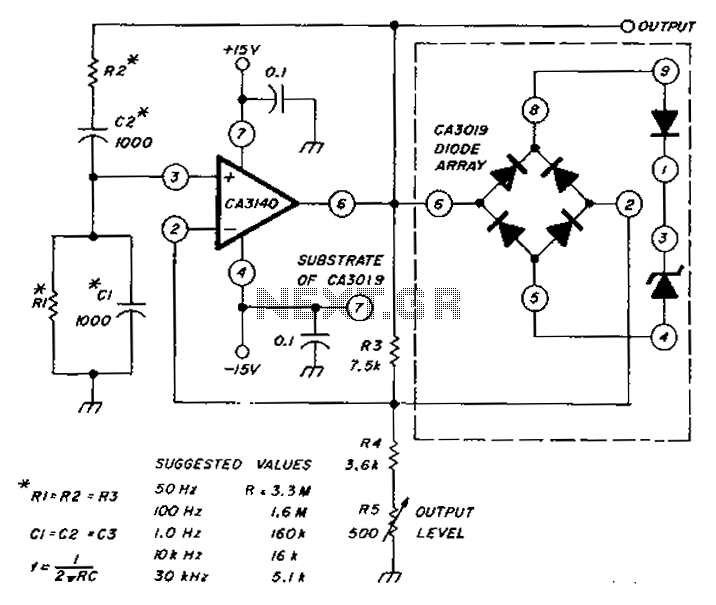
The circuit diagram utilizes a CA3140 operational amplifier and a diode array to generate a low distortion sine wave. A table specifies the values of resistors (R) and capacitors (C), enabling frequency access ranging from 50 Hz to 30...
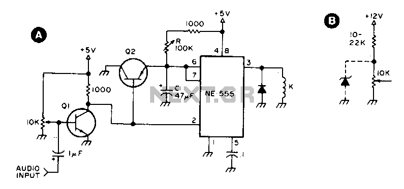
Q1 and Q2 are general-purpose transistors. The 10 kΩ input potentiometer is adjusted to a point just short of where Q1 turns on, as indicated by relay K engaging. K is any 5 V reed relay. With the specified...
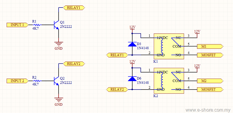
The circuit utilizes two sets of relays for each motor to switch the motor's direction, and one set of MOSFETs for each motor to control the motor's speed. The MOSFET and relay circuit will be divided into three parts...
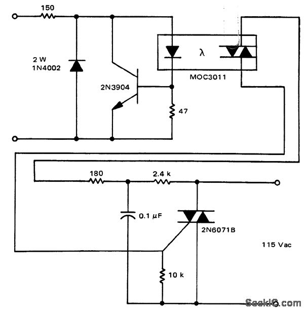
A solid-state relay circuit features an input protection mechanism utilizing the MOC3011 triac driver. The input voltage for the protection circuit can range from 3 to 30 volts DC, as noted by Motorola Semiconductor Products Inc. The solid-state relay (SSR)...
An astable multivibrator, also known as an oscillator circuit, operates on the principle of positive feedback. This type of circuit can be constructed using operational amplifiers, logic gates, or transistors. An astable multivibrator is a fundamental electronic circuit that generates...
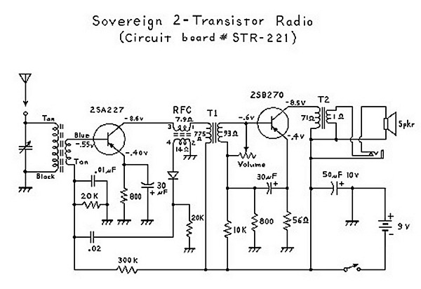
An analysis of certain radios reveals the impressive engineering by Japanese designers, particularly in creating a radio capable of driving a speaker with only two transistors. The first transistor (Q1) serves a dual function; it operates as an RF...