
Transistor Pin Identifier
The described circuit serves as a polarity tester for transistors and diodes, utilizing a three-phase oscillator circuit to facilitate the testing process. The core of the circuit is based on a 350Hz ring oscillator composed of three operational amplifiers (IC1A, IC1B, and IC1C). This oscillator generates a three-phase output that is crucial for testing the polarity of semiconductor devices.
The output from the oscillator is connected to the device under test (DUT) through a series of light-emitting diodes (LEDs). The circuit is designed such that during each one-third cycle of the oscillator, the DUT can be subjected to forward bias, reverse bias, or left unbiased. This method allows for a comprehensive evaluation of the device's characteristics.
The current flow through the DUT is monitored by two different colored LEDs: a Red LED and a Green LED. When current flows into the device, the corresponding Red LED illuminates, indicating that the device is in a forward-biased state. Conversely, when current flows out of the device, the Green LED lights up, signifying a reverse-biased condition. This visual feedback aids in determining the correct orientation of the transistor's base lead and verifying the polarity of the semiconductor device.
Additionally, the circuit employs further integrated circuits (IC2A, IC2B, and IC2C) to control the current through resistors R7, R8, and R9, which likely serve to limit the current to the LEDs and protect the circuit components. The entire system operates on a simple 9V battery, making it portable and easy to use in various testing environments.
Overall, this circuit provides a practical solution for testing transistors and diodes, offering clear visual indicators of device polarity and functionality through an efficient and straightforward design.Tests transistors and diodes for polarity. A three-phase wave form is derived from the 350Hz ring-of-three oscillator formed by IC1A, IC1B and IC1C, and applied to the device under test via the LEDs. The oscillator wave form enables each pair of device terminals to be forward, reverse and unbiased for one third of a cycle.
Simple circuitry - 9V Battery operation. Current flowing into the device will turn the appropriate Red LED on and current flowing out will turn on the Green LED. Thus, the position of the Base lead and the polarity of a transistor may be deduced. IC2A, B and C are used to switch R7, R8 and R9 a 🔗 External reference
Related Circuits

The circuit involves infrared phototransistor pairs positioned at three locations within a maze, including the endpoint. The maze is designed to be narrow enough for a single finger to slide through, and as fingers pass the phototransistors, a sound...

A bootstrapping input shield for a follower reduces cable capacitance, leakage, and spurious voltages resulting from cable flexing. Instability can be mitigated by using a small capacitor on the input. The bootstrapping input shield is a critical component in electronic...
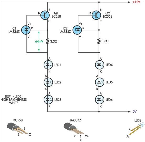
This LED lamp was originally designed for use in a budget solar-charged 12V electrical system. It provides sufficient brightness for comfortable reading at night. The LED lamp operates on a 12V power supply, making it suitable for integration into solar-powered...

The following circuit illustrates a flashing LED egg timer circuit diagram. This circuit utilizes 2N2646 transistors and features an MPF112 FET. The flashing LED egg timer circuit operates as a visual timer, providing an indication of elapsed time through the...
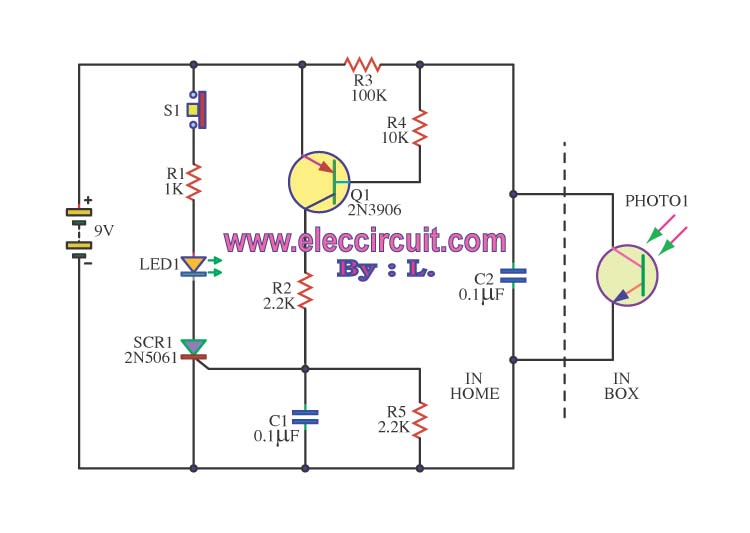
This is an integrated electronic mailbox circuit diagram designed for a front door. It activates when the door is opened. Additionally, when the cabinet photo detector is exposed to light, it will... The integrated electronic mailbox circuit is designed to...

Figure 2-33 (a) illustrates the schematic diagram of a robot approaching an object. When no objects are detected in front of the robot, it moves forward in a straight line. If an object is detected on the left or...