
Cable bootstrapping
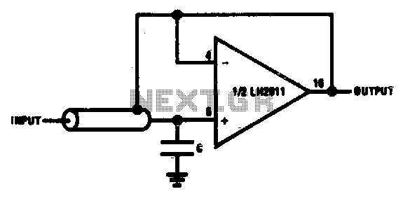
The bootstrapping input shield is a critical component in electronic circuits designed to improve signal integrity and reduce unwanted noise. This shield acts as a buffer, isolating the input signal from the effects of cable capacitance and leakage currents that can distort the signal during transmission. By minimizing these effects, the shield ensures that the follower circuit operates with greater accuracy and stability.
The design of the input shield typically incorporates a small capacitor placed strategically at the input stage. This capacitor serves to filter out high-frequency noise and stabilize the voltage levels, thereby preventing fluctuations that could lead to instability in the follower circuit. The value of the capacitor is chosen based on the specific application and the characteristics of the signal being processed.
In practical applications, the bootstrapping input shield is particularly beneficial in environments where cable movement is common, as it effectively reduces the spurious voltages generated by flexing cables. This is essential in maintaining the performance of sensitive electronic devices, such as audio equipment or precision measurement instruments, where signal fidelity is paramount.
Overall, the implementation of a bootstrapping input shield not only enhances the performance of follower circuits but also extends the longevity and reliability of electronic systems by mitigating the adverse effects of cable-related issues.Bootstrapping input shield for a follower reduces cable capacitance, leakage, and spurious voltages from cable flexing Instability can be avoided with small capacitor on input. 🔗 External reference
Related Circuits
I built this cable for my Casio QV-200 digital camera, it should work for many Casio models. It's basically an inverting buffer/converter to/from RS-232 voltage levels from/to CMOS levels. Why Casio didn't put this inside the camera like everyone...
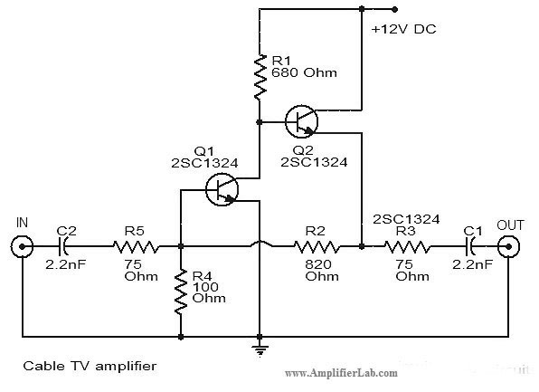
The circuit diagram of a cable TV amplifier has been provided. This cable TV amplifier circuit includes two transistors, Q1 and Q2. The cable TV amplifier circuit is designed to enhance the signal strength of cable television signals, improving the...
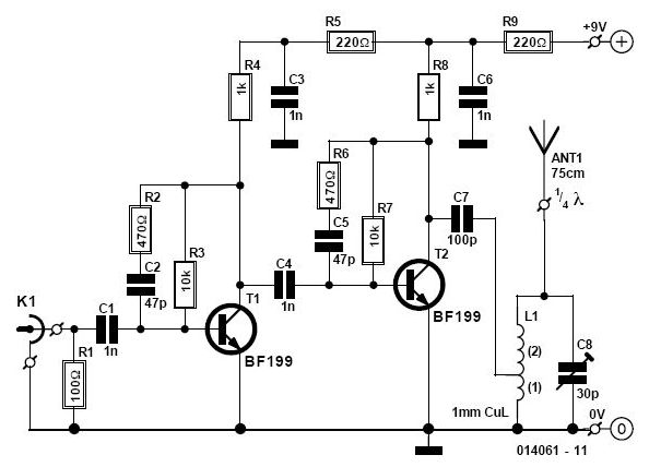
This circuit enables the use of a portable VHF FM radio to receive audio from stations that exclusively broadcast on the local cable network. This circuit operates by modulating the audio signals from the local cable network onto a carrier...
This simple cable tester can be used to check two-wire cables such as coaxial cables, telephone cables, audio cables, and others. The circuit is powered by a 9V battery. To operate, plug in the cable and press the "TEST"...
The most essential accessory for astrophotography, after a camera, telescope, and mount, is a remote shutter release to minimize vibration. A remote control is even more advantageous if it can trigger a series of exposures at preset intervals and...
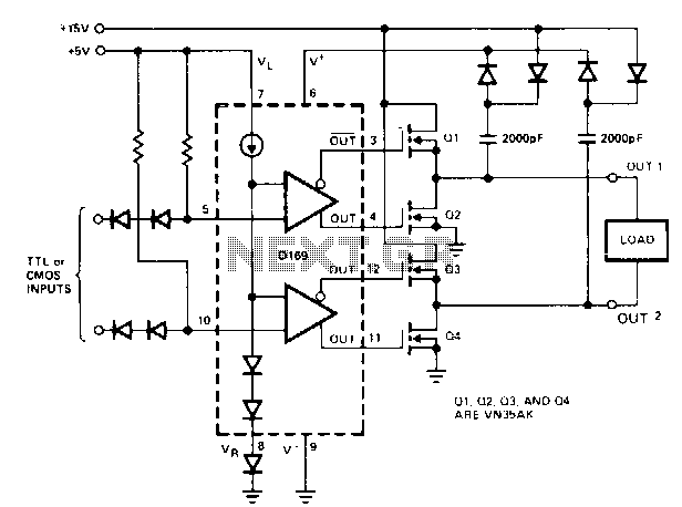
When driving MOSPOWER in a totem-pole output configuration, it is essential to maintain a gate voltage of 10 to 15 V positive relative to the source to manage load currents close to the maximum ratings of the MOSPOWER device....