
Universal Triac Control with Optocoupler
The universal triac controller circuit is designed to enhance the performance of triacs, particularly in low-temperature environments where standard operation may be compromised. The circuit employs an optocoupler to provide electrical isolation between the control side and the load side, ensuring safe operation and protecting sensitive components from high voltage spikes.
The configuration typically includes a triac, an optocoupler, resistors, and capacitors. The optocoupler is used to control the gate of the triac, allowing for low-voltage control signals to manage higher voltage loads. This is particularly advantageous in applications where the control circuit operates at a lower voltage, such as microcontrollers or digital logic circuits.
In the circuit, the optocoupler's LED is driven by the control signal, which activates the phototransistor on the output side. When the phototransistor conducts, it triggers the gate of the triac, allowing current to flow through the load. The use of a resistor in series with the LED ensures that the optocoupler operates within its specified current limits, while additional components may be employed to filter noise and stabilize the circuit.
For optimal performance, it is crucial to select a triac that matches the load specifications, including voltage and current ratings, and to ensure that the optocoupler is capable of providing sufficient gate current to trigger the triac reliably. This configuration not only improves the reliability of the triac operation in low-temperature conditions but also enhances overall circuit safety and efficiency.This universal triac controller circuit with optocoupler solves the problem that triacs have when functioning at low temperatures (triac needs higher gate. 🔗 External reference
Related Circuits
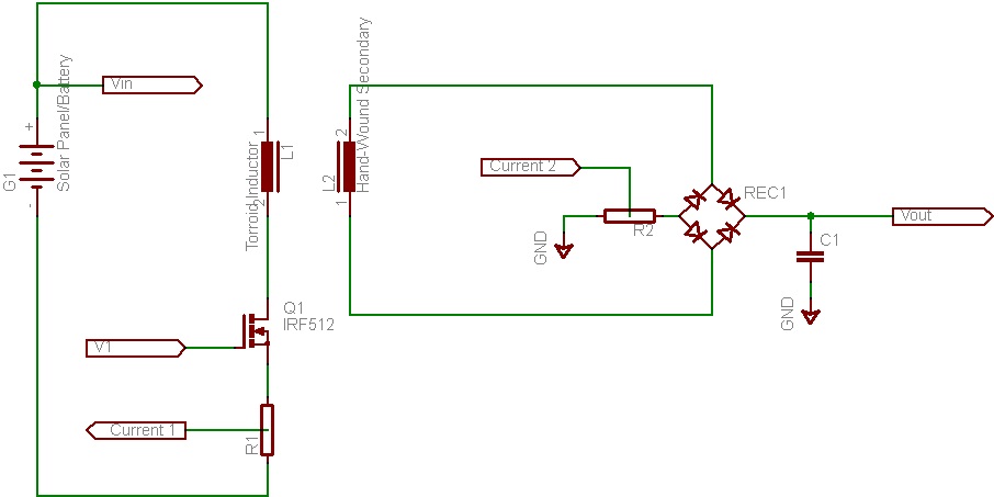
This document discusses the future direction of the Free Charge Controller project and proposes a new solar charge controller circuit. The Free Charge Controller project aims to enhance the efficiency and effectiveness of solar energy management systems. The proposed solar...
The MAXQ3210 is a powerful RISC microcontroller. This device has features and capabilities that make it suitable for battery-powered applications that require detection. The MAXQ3210 microcontroller is designed with a focus on low power consumption and efficiency, making it particularly...
The laser-pointer detection circuitry is capable of identifying when a laser light is directed at a specific photosensor. If the laser targets the top sensor, the comparator chip outputs a high signal. Conversely, if the laser is aimed at...
The controller circuit illustrated in Figure 15-24 consists of a switch-type Hall integrated circuit DN838 and an astable multivibrator, which is based on the 555 timer IC. This circuit is suitable for various applications, including automatic door opening, delay...
This integrated circuit is highly efficient and does not require any external glue logic for operation. It features two pins for motor control: one pin is dedicated to controlling the direction of the motor, while the other pin is...
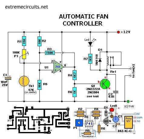
Transistor Q1 can be a 2N2222(A), 2N3904, NTE123A, ECG123A, etc. Not critical at all. It acts only as a switch for the relay so almost any type will work, as long as it can provide the current needed to...