
Tremolo Circuit
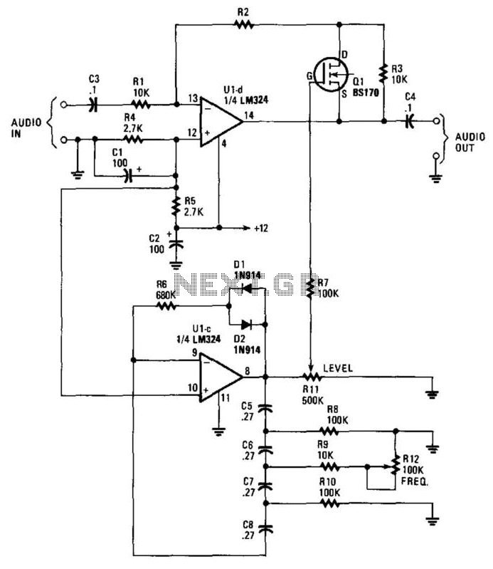
The circuit operates by leveraging a phase-shift oscillator (U1C) that produces a low-frequency oscillation. This oscillator typically consists of an operational amplifier configured in a feedback loop that introduces phase shifts to create a sine wave output at a frequency in the range of a few Hertz. The output of U1C is fed to transistor Q1, which acts as a modulator. The modulation of the gain of U1D is achieved by varying the control voltage applied to its input, influenced by the oscillating signal from Q1.
Resistor R11 plays a critical role in controlling the depth of the modulation effect. By adjusting R11, the user can increase or decrease the amplitude of the modulation signal, thus altering how pronounced the VLF AM effect is on the audio signal. A higher resistance value will result in a subtler effect, while a lower value will yield a more pronounced modulation.
Resistor R12 is responsible for adjusting the frequency of the modulation effect. Changing the resistance value alters the feedback network of the phase-shift oscillator, which in turn modifies the frequency of the oscillation. This allows for a range of modulation frequencies to be selected, enabling the user to tailor the sound to their preferences.
Overall, this circuit design is beneficial for musicians and sound designers looking to incorporate unique modulation effects into their audio signals, enhancing the sonic characteristics of their instruments or audio production. Proper implementation of the circuit components and careful tuning of R11 and R12 can yield a wide variety of creative sound effects. This circuit adds a VLF AM component to an audio signal. This effect is widely used in musical instruments. U1C, a phase-sh ift oscillator operating at a few Hz applies a signal to Ql, which modulates the gain of U1D. Rll varies the level of the effect, while R12 varies the frequency. 🔗 External reference
Related Circuits
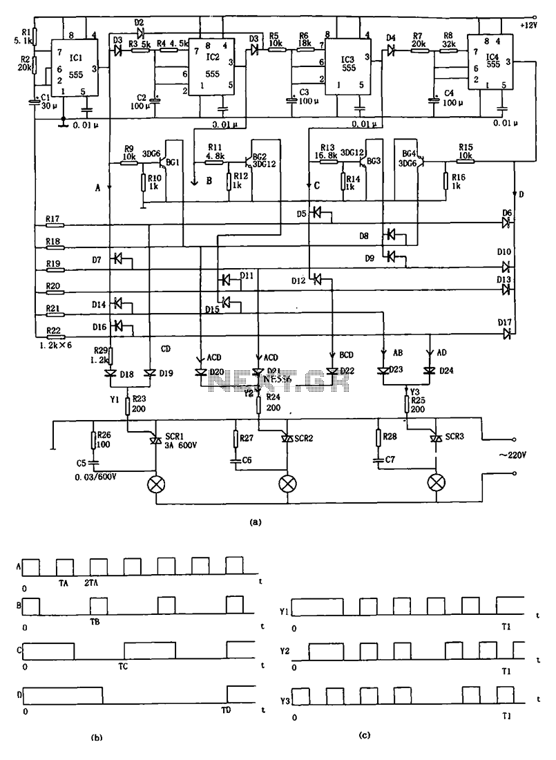
The decorative lamp control circuit is illustrated in the figure. The controller comprises a pulse generator, a frequency divider, a matrix circuit, and a thyristor control circuit. Components IC1, R1, R2, C1, and others form a multivibrator where the...
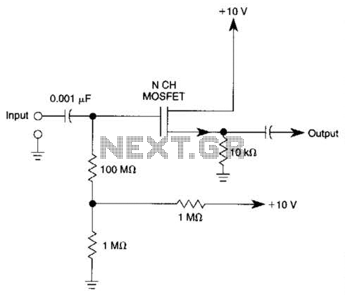
Biasing methods for an N-channel MOSFET to form a unity-gain noninverting amplifier or source-follower. The N-channel MOSFET can be utilized in various configurations, with one common application being the unity-gain noninverting amplifier, also known as a source-follower. In this configuration,...

The ESR Meter is essentially an AC Ohmmeter equipped with specialized scales and protective circuitry. It provides continuous readings of series resistance in electrolytic capacitors. Operating at 100 kHz, it maintains the capacitive reactance factor close to zero. The...
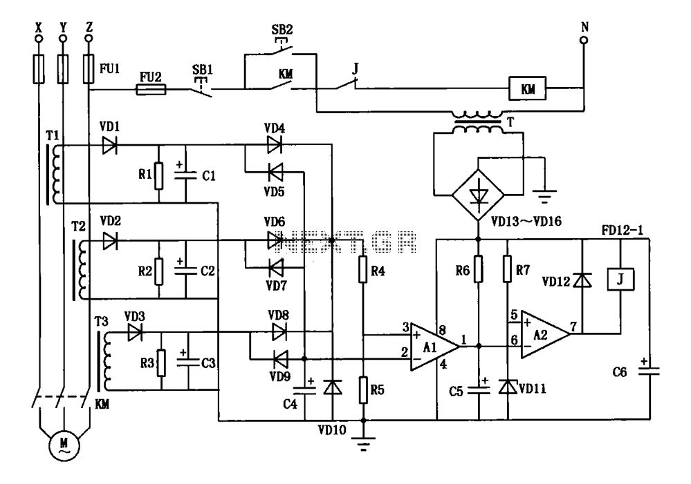
A current three-phase motor phase protection circuit is designed to detect three-phase current using homemade small current transformers T1, T2, and T3. The current signals are collected by rectifiers VD1, VD2, and VD3, while capacitors C1, C2, and C3...

The clock pulses from the 555 astable circuit are sent into the 4017 decade counter. Each output becomes high in turn as the clock pulses are received. Appropriate outputs are combined with diodes to supply the amber and green...
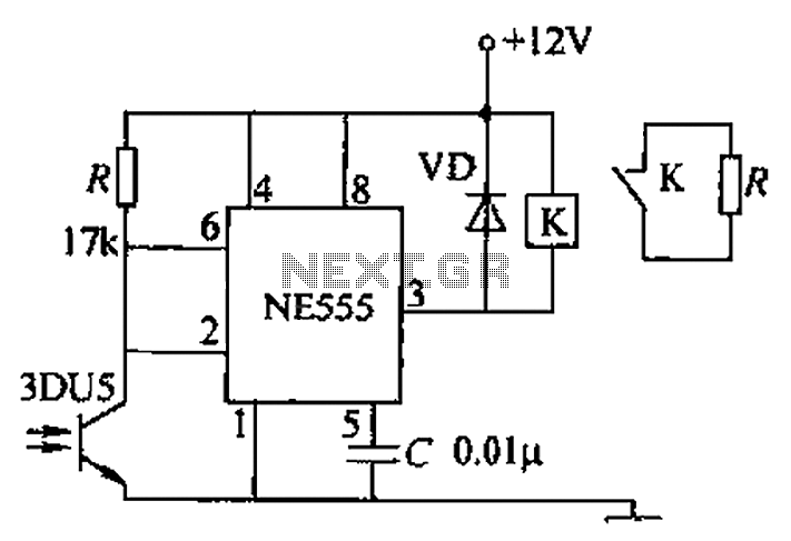
A transmitting circuit powered by an infrared light-emitting diode emits light. The receiving circuit, shown in the figure, utilizes a transistor (3DU5) to receive the infrared light and output the received signal. The signal is sent to terminal 3...
Warning: include(partials/cookie-banner.php): Failed to open stream: Permission denied in /var/www/html/nextgr/view-circuit.php on line 713
Warning: include(): Failed opening 'partials/cookie-banner.php' for inclusion (include_path='.:/usr/share/php') in /var/www/html/nextgr/view-circuit.php on line 713