
AC Ohmmeter ESR Meter Circuit

The ESR Meter circuit is designed to accurately measure the equivalent series resistance (ESR) of electrolytic capacitors, which is critical for assessing the performance and health of these components in various electronic applications. The operational amplifiers play a pivotal role in signal processing, with the regenerative oscillator providing a stable frequency reference essential for capacitance measurements. The choice of 100 kHz as the operating frequency is strategic; it ensures that the reactance of the capacitor being tested is minimized, allowing for precise resistance readings.
The configuration of op-amps IA and IB as a regenerative oscillator is crucial for generating the test signal. The timing capacitor C1, in conjunction with resistor R1, defines the oscillation frequency, which is critical for ensuring that the ESR Meter operates within the desired range. The use of diodes D2 and D3 to clip the output waveform is an important feature, as it prevents distortion of the signal due to variations in the power supply voltage, thereby enhancing measurement accuracy.
The test setup, which includes the 10-ohm source and load resistors, is designed to facilitate the measurement of the voltage drop across the load resistor R9F, which is directly proportional to the ESR of the capacitor under test. The blocking capacitor C3 ensures that only the AC component of the signal is measured, while the protective diodes D4 and D5 provide additional safety against transient currents that could damage the circuit components.
The amplification stages provided by op-amps ID, IC, and IIA are configured to ensure that the signal is sufficiently amplified for accurate reading on the meter display. The feedback resistors R13F and R14F are selected to achieve the desired gain, allowing for a linear response across a range of ESR values. This careful design and selection of components contribute to the reliability and effectiveness of the ESR Meter in practical applications, making it an essential tool for electronics engineers and technicians.The ESR Meter is basically an AC Ohmmeter with special scales and protective circuitry. It provides a continuous reading of series resistance in electrolytic capacitors. It operates at 100 kHz to keep the capacitive reactance factor near zero. Here`s the figure of the one design circuit for ESR meter circuit; The ESR meter uses 8 operational ampli fiers. An op-amp is an idealized basic amplifier with two inputs. The non-inverting input (+) has an in-phase relationship with the op-amp output, and the inverting input (-) an out-of-phase relationship. Op-amps are usually used with negative feedback and reach a stable operating condition when their two inputs are equal in voltage.
Op-amps IA & 1B form a regenerative 100 kHz oscillator circuit. Capacitor C1 is the basic timing capacitor and RI is selected to set frequency. Diodes D2 & D3 clip the bottom and top of the output waveform so that the output level and frequency are resistant to battery voltage changes. The oscillator output of op-amp 1B drives 10-ohm source resistor R8F. The test-capacitor, thru the test leads, couples this 100 kHz signal to 10-ohm load resistor R9F. The amount of voltage developed here is indicative of the capacitors ESR value. (The 10-ohm resistors determine the basic meter scaling. ) Capacitor C3 blocks any DC voltage present on the test-capacitor. Diodes D4 & D5 protect the ESR Meter from any initial charging current to C3. Resistor R7 discharges C3 after test. A DC operating bias of 0. 55 V is established by diode D1 for the oscillator stage and for all subsequent stages, which are DC coupled and operated class A.
DC bias from D1 and ESR signal from R9F are combined at the input of op-amp 1D. Both voltages are amplified by 1D, 1C, & 2A. Each of these three stages has an amplification factor of about 2. 8 due to the ratio of output-voltage to feed back voltage at the (-) input, which is determined -by feedback resistors R13F & R14F, etc. 🔗 External reference
Related Circuits
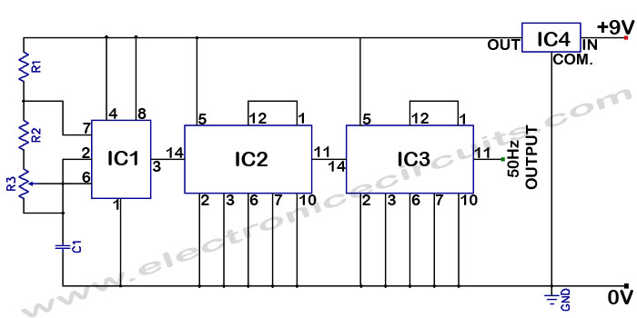
Accurate 50Hz Oscillator Circuit Using 555 and 7490. This circuit generates a 50Hz pulse. It consists of a 555 timer and two 7490 divide-by-ten counters. The circuit utilizes a 555 timer configured in astable mode to produce a square wave...
The circuit is designed for high precision operation over an extended temperature range, provided that V+ remains relatively constant, as the current IZ is dependent on V+. Resistors R1, R2, R3, and R4 are selected to ensure the appropriate...
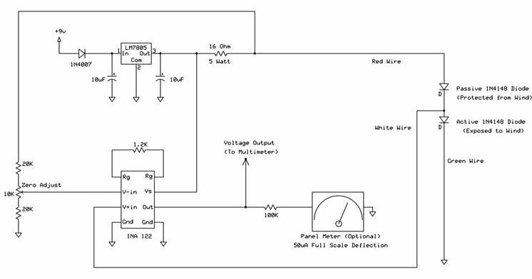
The following circuit illustrates a wind speed indicator circuit. It operates with a constant 5 VDC output provided by the LM7805 voltage regulator, using a 9 VDC supply. The wind speed indicator circuit is designed to measure and display wind...
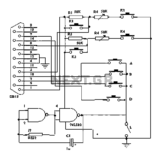
The principle of the dancing blanket is straightforward; it functions as a direct retrofit for a keyboard or gamepad. Each key on the keyboard and gamepad operates as a switch, which connects to the ground through a wire lead....
The following circuit illustrates a LEGO Light Sensor Circuit Diagram. This circuit is based on the LM358 integrated circuit, which features a dual operational amplifier and high-speed capabilities. The LEGO Light Sensor Circuit utilizes the LM358, a versatile dual op-amp...

This is a simple power supply that provides a reliable and clear regulated output voltage ranging from 0 to 28 volts with a maximum current of 6 to 8 amperes. Utilizing two 2N3055 transistors allows for doubling the output...