
Triac regulation of mains voltage
Triac regulation circuits are essential for controlling the power delivered to various electrical devices, allowing for a versatile range of applications in home and industrial settings. The triac functions as a semiconductor switch, enabling precise control over the power output by adjusting the phase angle of the AC waveform. This method of control is particularly effective for resistive loads like incandescent bulbs and heating elements, where the power can be smoothly varied without introducing significant harmonic distortion.
The use of the integrated circuit U2008B enhances the reliability and performance of the circuit, providing a robust control mechanism for the triac. The circuit design must consider the thermal management of the triac, as excessive heat can lead to failure. Therefore, adequate heatsinking is necessary for high-power applications, ensuring that the triac operates within its specified temperature range.
The circuit's safety features are paramount, given the high voltages involved. The recommendation to use a potentiometer with a plastic shaft minimizes the risk of electric shock, while the note regarding the non-isolated metal case of the triac serves as a crucial reminder for proper handling and installation practices. All components should be rated for the expected electrical loads and voltages to maintain circuit integrity and safety.
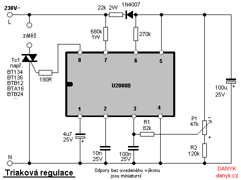
In summary, the triac regulation circuit provides a practical solution for controlling the power of various electrical appliances, combining effective performance with necessary safety considerations. Proper component selection, circuit design, and adherence to safety protocols are essential for successful implementation in real-world applications.Triac regulation suited to regulate the power of mains appliances. It can regulate the brightness of incadescent light bulbs, halogen, dimmable energy savers, the power of heaters and other thermal appliances, engine (motor) regulation, etc. Fits as well to regulate certain types of Tesla transformer (eg SSTC). Power can be easily ad justed from 0 to 100% by simply turning the potentiometer. Triac regulation uses the triac as a switching element. Triac is triggered at some phase by pulse to the control electrode G (Gate) and remains conductive until the line passes zero voltage. There are also some regulators made of discrete components, but as the most reliable I found the involvement of an integrated circuit U2008B.
The schematic diagram below shows triac regulation circuit for 220V / 230V / 240V mains voltages. Power is adjusted by P1. If the regulations does not regulate in full range, adjust R1 or R2. The triac operates in quadrants II and III. Caution - note that the electrolytes in the diagram have positive pole at neutral. The resistors with no wattage noted are miniature. Triac Tc1 has to be sufficiently dimensioned according to the load. For higher powers, place it on the heatsink. You can use for example BT134, BT136 to 4A, BTB12 to 12A, BTA16 to 16A or BTB24 to 24A. Triac must also be rated to sufficient voltage, I recommend at least 600V. Warning: The whole circuit is at mains voltage! To ensure safety, it is necessary to use suitable potentiometer (with plastic shaft). Metal case of triac is not isolated from the mains! Connected appliance should always be treated as live, even if the regulation is set to zero power. The appliance is still under voltage! 🔗 External reference
Related Circuits
Occasionally, a small high-voltage power supply is required for various projects without the need for specialized transformers or specific chips. A simple circuit diagram for a classical step-up converter based on the widely used 555 timer was found online....
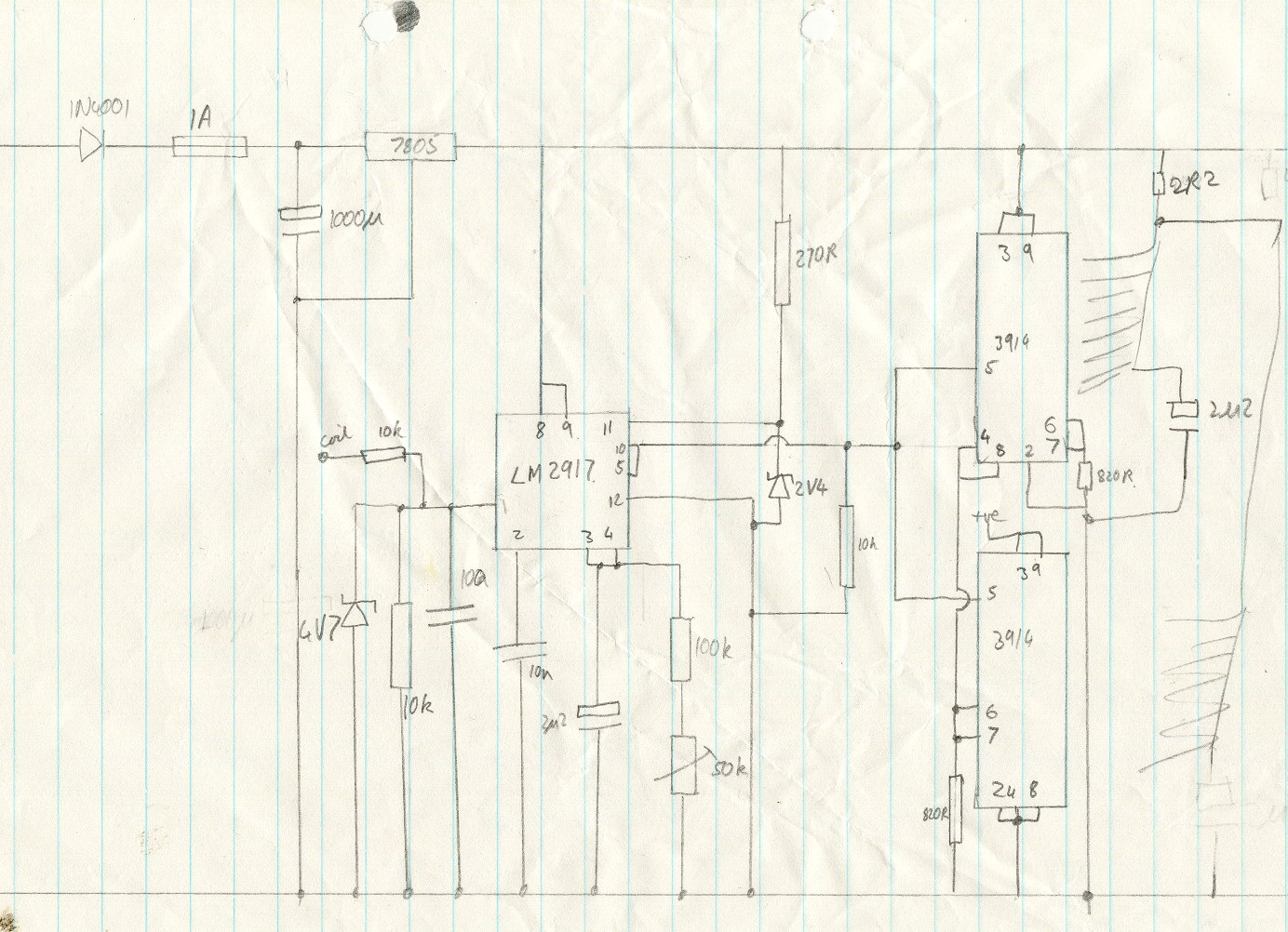
This circuit utilizes an LM2917 frequency-to-voltage converter. The input is connected to the low voltage side of the ignition coil, with various components designed to produce a full-scale output at 6000 RPM, corresponding to 12000 ignition pulses per minute,...
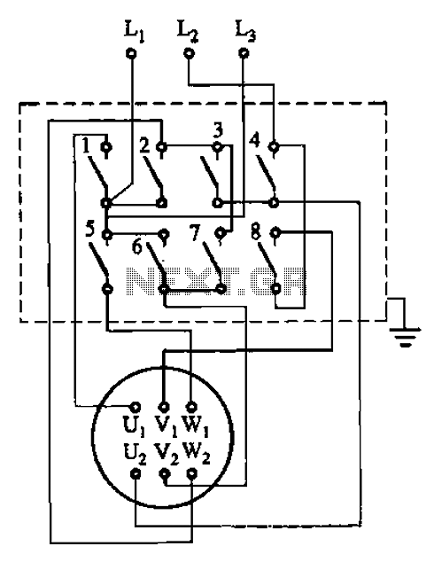
The circuit illustrated in Figure 3-36 includes the starter contact closure detailed in Table 3-1. In the figure, U1, V1, W1, and U2, V2, W2 represent the first three-phase stator windings of the motor terminals. The circuit depicted in Figure...
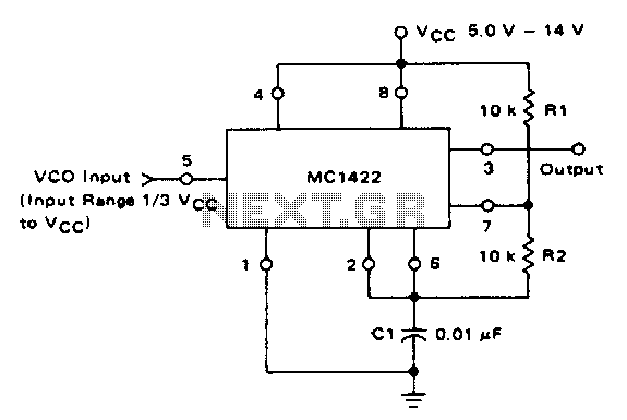
The VCO circuit, which has a nonlinear transfer characteristic, will operate satisfactorily up to 200 kHz. The VCO input range is effective from V% Vcc to Vcc - 2 V, with the highest control voltage producing the lowest output...
The task involves converting a relay in a design to a triac. The circuit switches a 120V nichrome wire with a resistance of 60 ohms. The circuit is powered by a 12V transformer, and there is a 120V neutral...
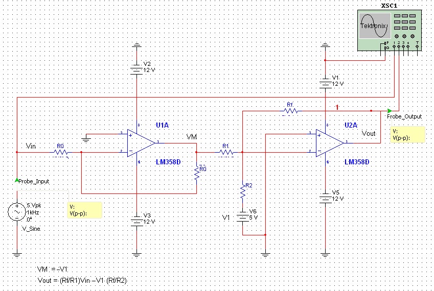
All naturally occurring phenomena such as sound, temperature, and pressure are analog in nature. To enable a microcontroller to read analog signals for the analog-to-digital conversion process using a built-in analog-to-digital converter (ADC), it is essential to condition the...
Warning: include(partials/cookie-banner.php): Failed to open stream: Permission denied in /var/www/html/nextgr/view-circuit.php on line 713
Warning: include(): Failed opening 'partials/cookie-banner.php' for inclusion (include_path='.:/usr/share/php') in /var/www/html/nextgr/view-circuit.php on line 713