
Triangle Wave Generator
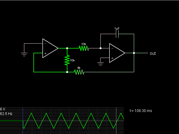
The described circuit primarily functions as an inverting integrator, which is a fundamental component in analog signal processing. The operational amplifier used in this configuration is critical for its ability to amplify voltage differences. Initially, the op-amp's non-inverting input is set to a voltage slightly above ground, which allows it to amplify the input difference significantly. The output voltage swings to the positive power supply limit (15 V), which indicates that the circuit is in a charging state.
The integration process is facilitated by the feedback network formed by the resistors. The 10kΩ and 4kΩ resistors create a voltage divider that stabilizes the non-inverting input of the first op-amp. This configuration ensures that the input voltage to the op-amp is carefully controlled, allowing for predictable behavior as the integrator processes the input signal.
As the output of the integrator decreases, it does so at a constant rate, which is characteristic of integration in an analog circuit. The output voltage will continue to drop until the voltage at the non-inverting input reaches ground. At this point, the op-amp's output will switch polarity, causing the integrator to reverse its output direction. This transition effectively creates a triangular waveform, as the output voltage will rise and fall in a linear fashion.
The cycle continues as the op-amp toggles between its output states, generating a continuous triangular waveform. This behavior is essential in various applications, including waveform generation and signal modulation. The precise values of the resistors can be adjusted to modify the integration rate and the frequency of the output waveform, providing flexibility in circuit design for specific applications.The second half of the circuit is an inverting integrator. The first op-amp starts with its two inputs in an unknown state; let`s say it starts with + slightly higher than (which is at ground). The op-amp greatly amplifies this difference, bringing its output to the op-amp`s positive power supply voltage, its maximum output (15 V in this case)
. With this positive input, the integrator`s output falls at a constant rate. The 10k and 4k resistors act as a voltage divider which put the first op-amp`s + input 4/14ths of the way from the second op-amp`s output to the first op-amp`s output. When this input reaches ground, then the first op-amp`s output switches polarity, and the integrator switches direction, forming the other half of the triangle.
When the first op-amp switches polarity again, a new cycle begins. 🔗 External reference
Related Circuits
Cascading two identical integrators results in an overall phase shift of 180° and an amplification of unity, provided that the frequency is 1/2kRiCi. This configuration serves as an ideal basis for an oscillator. The two integrators are connected in...

This circuit is a delayed pulse generator that provides pulse rate and independent control of the initial delay. The pulse generator of this circuit is. The delayed pulse generator circuit is designed to produce a pulse output after a specified...
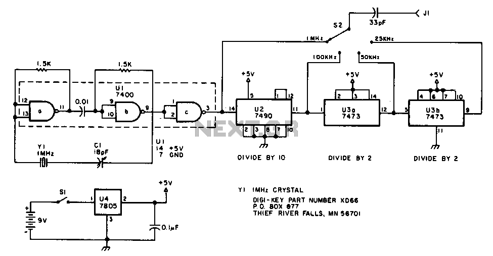
The oscillator section employs three sections of a 7400 quad NAND gate integrated circuit. The 1 MHz signal generated by the oscillator is input into a 7490 decade counter, which is configured to divide by ten, producing a 100...
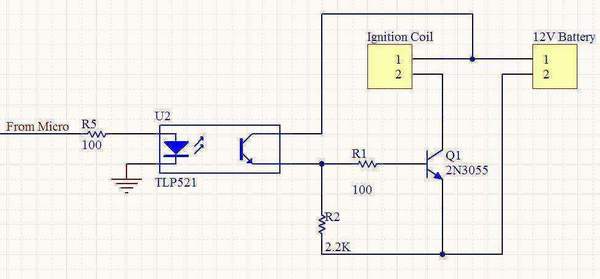
A 12V motorcycle battery and a car ignition coil are utilized in this project. A microcontroller generates pulses to the base of a 2N3055 transistor, which switches the primary of the ignition coil on and off, producing the desired...
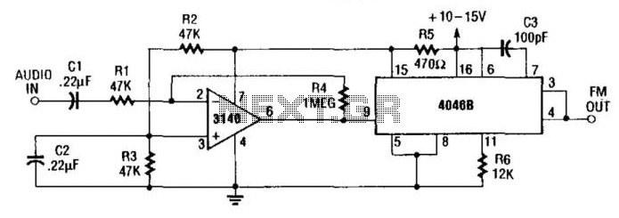
The internal zener diode on pin 15 of the 4046B provides a stable voltage to the 3140IC operational amplifier. This amplifier modulates the voltage-controlled oscillator (VCO) of the 4046B. The gain of the amplifier is approximately 20 (26 dB...
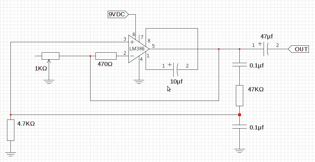
The design utilizes the LM386n-1 integrated circuit, powered by a single power supply to maintain a compact layout. There is a need to control the frequency, and the user is inquiring about which component values should be adjusted for...
Warning: include(partials/cookie-banner.php): Failed to open stream: Permission denied in /var/www/html/nextgr/view-circuit.php on line 713
Warning: include(): Failed opening 'partials/cookie-banner.php' for inclusion (include_path='.:/usr/share/php') in /var/www/html/nextgr/view-circuit.php on line 713