
Try signal conditioning the audio video for an RF modulator
The first step in addressing these requirements is implementing low-pass reconstruction filtering to suppress aliased outputs and out-of-band noise in the modulator's audio and video inputs. Active filters can elevate the DAC output to standard levels while driving the rear panel and the RF modulator. For audio, a low-pass filter (LPF) with a "3dB point of 22-24 kHz and sufficient gain to produce 2 VRMS at the rear panel is necessary. Assuming a gain of two, this can be achieved with a single passive RC filter. A second RC filter is designated for the audio modulator rather than reconstruction. The corresponding circuit (Figure 2) drives the rear panel outputs and the input to the audio section of the RF modulator. Video signal processing is more complex due to its lack of high oversampling, necessitating at least a 3-pole reconstruction filter. If this filter introduces excessive group-delay variation, compensation must be implemented, along with gain adjustments to address variations in the video DAC output and back-termination loss. The optimal solution is to utilize an active filter, with a suggested design for NTSC or PAL applications illustrated in Figure 3. These circuits offer the advantage of adjustable group delay (using R8) and can effectively drive the rear panel outputs.Despite the need for an IC, this ubiquitous interface between the modulator and audio-video signals has not been reduced to an integrated circuit. The major reasons for that deficiency are the difficulty of such a design, the variations required for different standards, and the variable levels required by the modulator itself.
The alternative to a n IC interface is a discrete design. The signal-conditioning requirements include lowpass and notch filtering of the video, group-delay compensation for the video, pre-emphasis for the audio, and (to adjust the modulation level) level controls for both audio and video. Because many cable and satellite receivers, VCRs, DVDs, and TVs don`t fully comply with these signal-conditioning requirements, the modulated signals of channels 3-4 have poorer quality than that of the baseband composite (Cvbs).
The discussion below explains the interface requirements and how to meet them using standard op amps and discrete components. The resulting low-cost circuitry can also provide rear-panel outputs for most audio/video (A/V) appliances.
For driving RF modulators in NTSC and PAL systems, the allowable video group-delay variation and required audio pre-emphasis are clearly specified by ITU Recommendation BT. 470-6. Most of the other specifications, not as obvious, are summarized and extrapolated to include other, unstated design specifications (Tables 1-2).
Those table entries are based on typical back-panel outputs for a TV, DVD, or set-top box having both baseband and RF-modulated A/V outputs (Figure 1). Some of these requirements depend on the source. If the signals to the modulator come from a DAC, for example, they obviously need reconstruction filtering to prevent out-of-band modulation and to remove artifacts, noise, and aliased signals.
In the general case, they must also be amplified to compensate for back-terminated loads and variation in the DAC outputs. The requirement to notch-filter the video around the audio subcarrier is not stated, but is implied by the group-delay adjustment described in Figure 3 of ITU-470.
Modulator chips usually recommend such notch filtering. Also requiring attenuation are the rear-panel signals, whose output levels are typically higher than required for the modulator inputs. These conditions lead to requirements for the Audio Video Interface of Figure 1: A sound-subcarrier bandstop or notch filter, centered on the sound subcarrier.
This filtering causes a large variation in group delay near the notch frequency. (To make this compensation possible, both NTSC and PAL place the sound subcarrier above the video`s minimum "3dB bandwidth. ) The first thing to be done is lowpass-reconstruction filtering, to suppress aliased outputs and out-of-band noise in the modulator`s audio and video inputs.
Active filters for that purpose let you raise the DAC output to standard levels while driving the rear panel and the RF modulator. Audio requires a lowpass filter (LPF) with a "3dB point of 22- 24KHz, and enough gain to produce 2VRMS at the rear panel.
We assume a gain of two, and because audio is highly over-sampled, the requirement can be met with a single passive RC filter. As explained later, the second RC filter is for the audio modulator, not reconstruction. This circuit (Figure 2) drives the rear panel outputs and the input to the audio portion of the RF modulator.
Video is more difficult. It isn`t highly over-sampled, and therefore requires at least a 3-pole reconstruction filter. If this filter causes excessive group-delay variation, you must compensate for it and add gain, to make up for variations in the video DAC output and back-termination loss. Again, the best solution is an active filter. A suggested design for NTSC or PAL applications is shown in Figure 3. (See Maxim`s application note on this. ) A benefit of these circuits is adjustable group delay (using R8), and their ability to drive the rear
🔗 External reference
Related Circuits
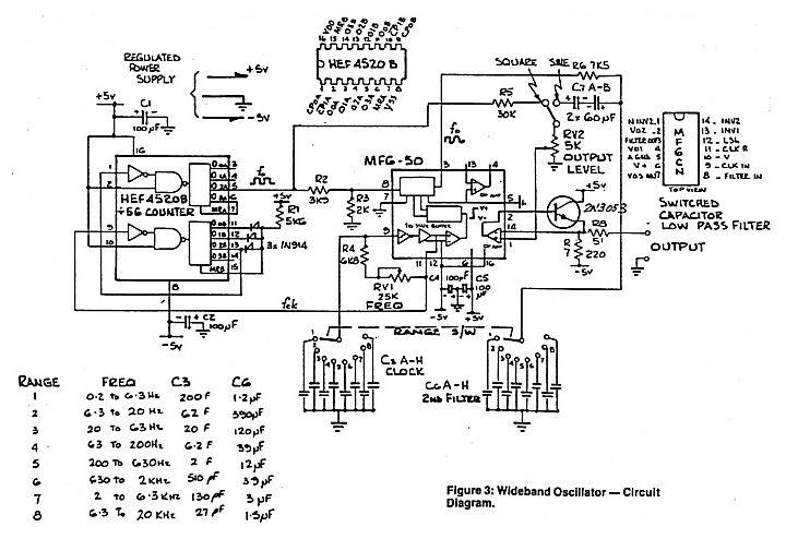
A low distortion audio frequency sine wave can be generated by passing the output of a simple square wave oscillator through a sharp cutoff low-pass filter to attenuate the odd harmonic components. The output level of the sine wave...
This contributed project is a result of considerable collaboration between Sergio and myself, and should not be seen as necessarily a complete project in itself, but a stepping stone to understanding switching power supplies, how they work, and what...
The 3-channel audio mixer is a compact application utilizing transistor amplifiers. This audio mixer operates with a supply voltage of 9V DC, which can be provided by a battery. It is designed specifically for use as a portable amplifier....
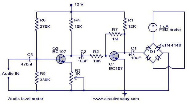
A simple audio level meter or Volume Unit (VU) level meter circuit with diagram and schematic. This sound level meter is designed using transistors with a flat frequency response in the range of 20Hz to 50kHz. The audio level meter...
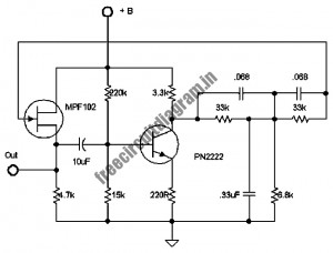
The following circuit illustrates a stable 60 Hz frequency signal generator circuit diagram. Features include a 0.068 µF capacitor incorporated within a feedback loop, allowing for DC-to-AC conversion. This circuit is designed to generate a stable 60 Hz sine wave...
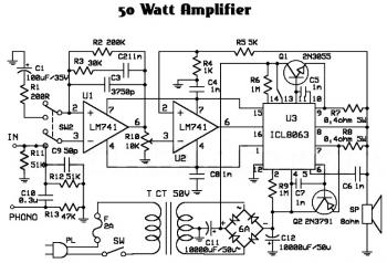
An audio amplifier is an electronic device designed to amplify low-power audio signals, which primarily consist of frequencies ranging from 20 Hz to 20,000 Hz, the human range of hearing. This amplification is necessary to drive loudspeakers and represents...