
Tunable notch filter to suppress hum
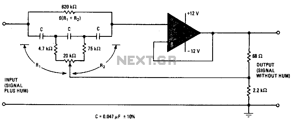
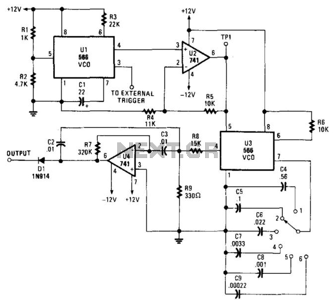
The described narrow stop-band filter is designed to eliminate specific frequency components from an input signal, particularly targeting power-line hum, which often manifests at 60 Hz (or 50 Hz in some regions). The filter's adjustable notch allows for fine-tuning, accommodating variations in the frequency of unwanted signals, making it versatile for various applications.
The circuit typically consists of a combination of resistors, capacitors, and a potentiometer. The potentiometer serves as a variable resistor that alters the filter's characteristics, allowing the user to set the notch frequency precisely within the specified range of 45 to 90 Hz. This adjustability is crucial for applications where the exact frequency of interference may vary.
The filter's design may employ a second-order or higher-order topology to achieve the desired attenuation level of at least 30 dB. This level of attenuation is significant enough to reduce the impact of noise on sensitive audio equipment or other electronic devices.
The use of wide-tolerance components contributes to the overall affordability of the circuit. While high-precision components can offer better performance, they often come at a higher cost. By utilizing components with wider tolerances, the circuit can maintain a balance between performance and cost-effectiveness, making it accessible for hobbyists and professionals alike.
In summary, this narrow stop-band filter is a practical solution for mitigating unwanted frequency interference, particularly from power-line sources, while remaining economical and easy to implement in various electronic projects.This narrow-stop-band filter can be tuned by the pot to place the notch at any frequency from 45 to 90 Hz. It attenuates power-line hum or other unwanted signals by at least 30 dB Because the circuit uses wide-tolerance parts, it is inexpensive to build. 🔗 External reference
Related Circuits
One of the limitations affecting all real amplifiers is the finite signal bandwidth. This implies that any amplifier constructed or utilized has an upper limit to the range of sinewave frequencies it can amplify. Consequently, high-frequency signals may not...
High-order filters are typically designed with two or more cascaded sections. An order 4 filter requires only one operational amplifier integrated circuit (OA IC), allowing for lower distortion. High-order filters are essential in various applications, including audio processing, signal conditioning,...
The circuit presented operates as a bandpass filter, with the transfer function derived from FBP(s) = 1 + s/Qo + s²/w₀². The cut-off frequency, denoted as ω₀, and the quality factor (Q-factor) are defined by ω₀ = g/C and...
When this circuit is connected to a filter and an oscilloscope, the oscilloscope displays the filter's frequency response. A frequency that sweeps from low to high is applied to a filter. An oscilloscope is triggered by the start of...
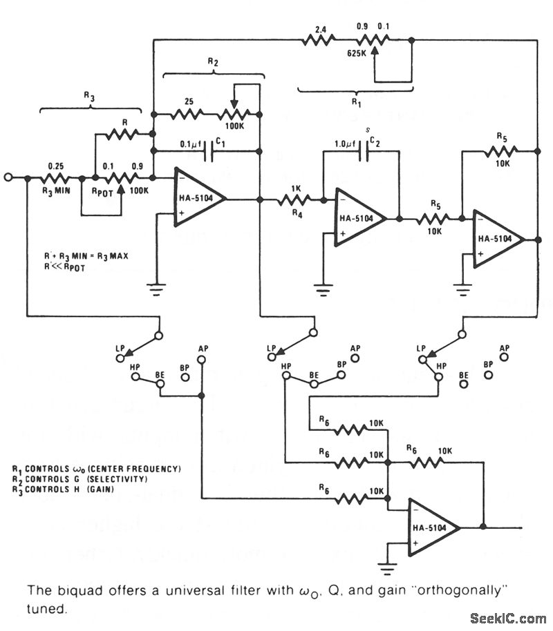
The Biquad consists of two successive integration stages followed by an inverting stage. The entire configuration includes a feedback loop from the front to the back, with resistor R1 primarily responsible for controlling the center frequency, fo. The first...
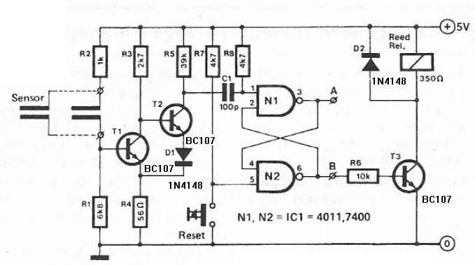
Humidity detector circuit electronic project using common electronic parts The humidity detector circuit is a project designed to measure and indicate the level of humidity in the environment. This circuit utilizes commonly available electronic components, making it accessible for hobbyists...