
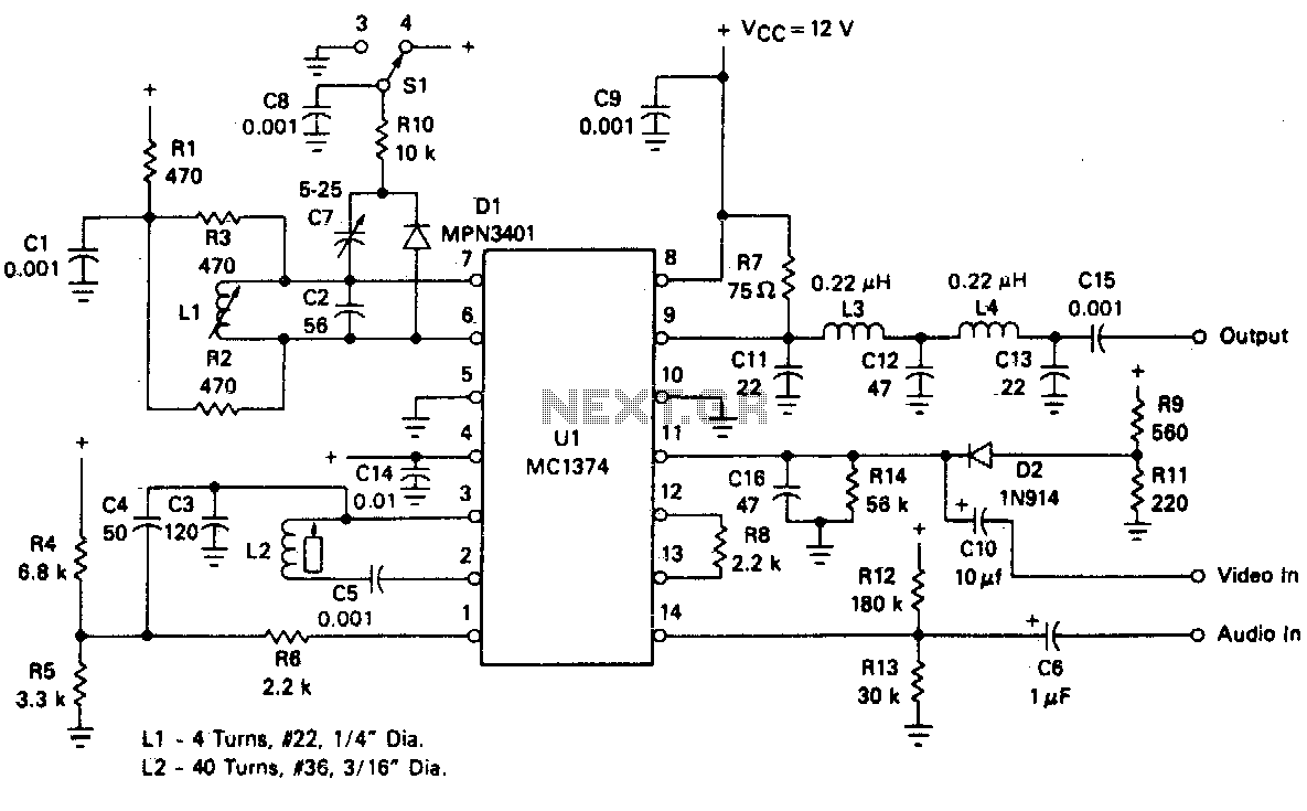
Tv modulator
The FM oscillator/modulator employs a voltage-controlled oscillator (VCO) design, which allows for precise frequency modulation based on the input voltage. This characteristic is essential for applications requiring stable and accurate frequency output, such as in communication systems and signal processing.
The circuit typically consists of a few key components, including an operational amplifier, capacitors, resistors, and a voltage reference. The operational amplifier is configured to create a feedback loop that stabilizes the oscillation frequency. The frequency can be adjusted by varying the input voltage, which alters the capacitance or resistance in the feedback loop, effectively changing the oscillation frequency.
The frequency range of 1 to 14 MHz makes this FM oscillator suitable for various applications, including amateur radio, telemetry, and other RF communication systems. The ability to produce a ±25 kHz deviation around a 4 MHz center frequency ensures compatibility with standard FM modulation requirements, allowing for clear signal transmission with low distortion.
Total harmonic distortion (THD) is a critical parameter in evaluating the performance of oscillators. This FM modulator achieves approximately 0% THD, indicating that the output signal is clean and free from unwanted harmonic frequencies, which is vital for maintaining signal integrity in communication systems.
In summary, the FM oscillator/modulator is a versatile and efficient device for generating frequency-modulated signals with minimal components, offering a wide operational frequency range and excellent signal quality. Its design is well-suited for various electronic applications, particularly in the fields of radio frequency and communication technology.The FM oscillator/modulator is a voltage-control led oscillator, which exhibits a nearly linear output frequency versus input voltage characteristic for a wide deviation. It provides a good FM source with a few inexpensive external parts It has a frequency range of 1 to 14 MHz and can typically produce a ±25 kHz modulated 4 MHz signal with about 0% total harmonic distortion. 🔗 External reference
Related Circuits

Two integrated circuit (IC) RF modulators are utilized to convert a suitable baseband video and audio signal into a low VHF modulated carrier, specifically channels 2 through 6 in the U.S. and channels 1 through 3 in Japan. The...
This circuit illustrates an FM modulator with a strong and weak signal switching mechanism. The circuit diagram 3-14 (a) depicts mechanical switches, including a worker selector switch that allows for signal strength selection. Figure 3-14 (b) demonstrates the implementation...
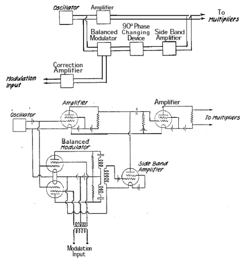
A system is being developed to transmit in the FM band. The oscillators have already been constructed to facilitate transmission across multiple frequencies. The design of an FM transmission system involves several key components, including oscillators, modulators, amplifiers, and antennas....
More: An electronic schematic is a representation of the components and connections within an electronic circuit. It serves as a blueprint for constructing electronic devices, allowing engineers and technicians to visualize how components interact and function together. The schematic...
This is a simple PWM modulator circuit. Comparing the message signal to a ramp or triangular waveform is the simplest way to produce a PWM signal. When the... The PWM (Pulse Width Modulation) modulator circuit operates by comparing a modulating...
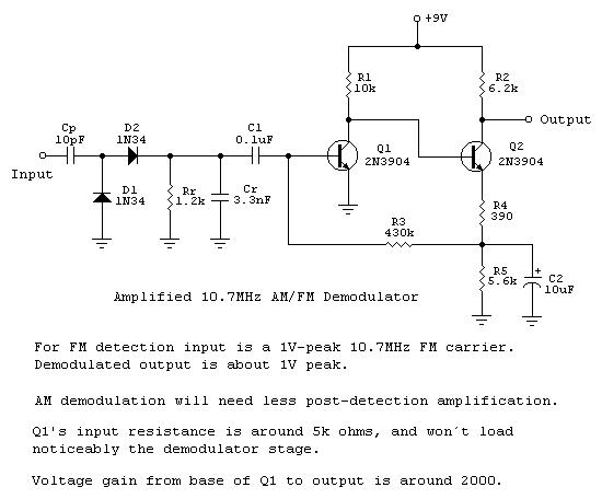
Frequency-to-voltage converters are integral components in various instrumentation circuits and are also utilized in radio applications as FM demodulators. A notable configuration for these applications is the Diode Charge Pump circuit (DCP), which additionally serves as an AM detector....
Warning: include(partials/cookie-banner.php): Failed to open stream: Permission denied in /var/www/html/nextgr/view-circuit.php on line 713
Warning: include(): Failed opening 'partials/cookie-banner.php' for inclusion (include_path='.:/usr/share/php') in /var/www/html/nextgr/view-circuit.php on line 713