
TV transmitter circuit using only 2 transistors operates from 12V

The described circuit utilizes two transistors to create a basic television transmission system capable of operating on a 12V power supply. The design is suitable for transmitting signals compatible with PAL B and PAL G television broadcasting standards, which are widely used in various regions.
The circuit typically consists of a pair of bipolar junction transistors (BJTs) configured to amplify the video signal. The first transistor acts as a modulator, where the input video signal is combined with a carrier frequency generated by an oscillator circuit. This modulation process allows the video signal to be transmitted over the airwaves.
The second transistor functions as a power amplifier, boosting the modulated signal to a level suitable for transmission. An LC circuit, composed of inductors and capacitors, is often included to filter and tune the output frequency to ensure compliance with the desired broadcasting standards. The output stage may also include an antenna, which radiates the amplified signal.
To ensure stable operation, proper biasing of the transistors is essential, often achieved through resistors connected to the base terminals. Additionally, decoupling capacitors can be employed to minimize noise and improve the overall performance of the circuit.
It is important to consider the layout of the circuit to minimize interference and maximize signal integrity. Shielding may be necessary to prevent unwanted pickup of signals, especially in environments with high electromagnetic interference.
This simple two-transistor TV transmitter circuit serves as an educational tool for understanding the fundamentals of television transmission and modulation techniques, while also providing a practical application for hobbyists interested in electronics and broadcasting.Simple two transistor TV transmitter circuit that operates from 12V.Compatible with PAL B and PAL G systems.. 🔗 External reference
Related Circuits
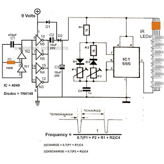
The 4049 section serves as a fundamental voltage doubler circuit, enhancing a 9 V supply to approximately 15 V. This elevated voltage subsequently acts as the supply voltage for the following 555 pulse modulator section. A key characteristic of...

The LEDs in the circuit light up sequentially and "dance" in response to the music level applied at the input, preferably from the speaker terminals of the audio device being monitored. This configuration is consistent across all LEDs in...

The PM4040F is utilized in switching power supply applications for medium power ranges. It is designed to drive power supplies between 200W and 800W, as illustrated in the accompanying bridge circuit. For power applications below 1000W, an alternative circuit...

This circuit design generates a stable 1 kHz sine wave using an inverted Wien bridge configuration with components C1-R3 and C2-R4. It offers a variable output, low distortion, and low output impedance to ensure good overload capability. The circuit...

The use of white LEDs for home illumination is gaining popularity due to their high power efficiency. The diagram illustrates a simple circuit configuration that consists of multiple LEDs arranged in both series and parallel. In the LED tube...

Infrared (IR) Motion Detector Circuit featuring a motion detector alarm and an infrared sensor. The circuit diagram and its operation are provided in detail. The infrared (IR) motion detector circuit is designed to detect motion within a specified range and...