
Twilight Lamp Blinker LDR project
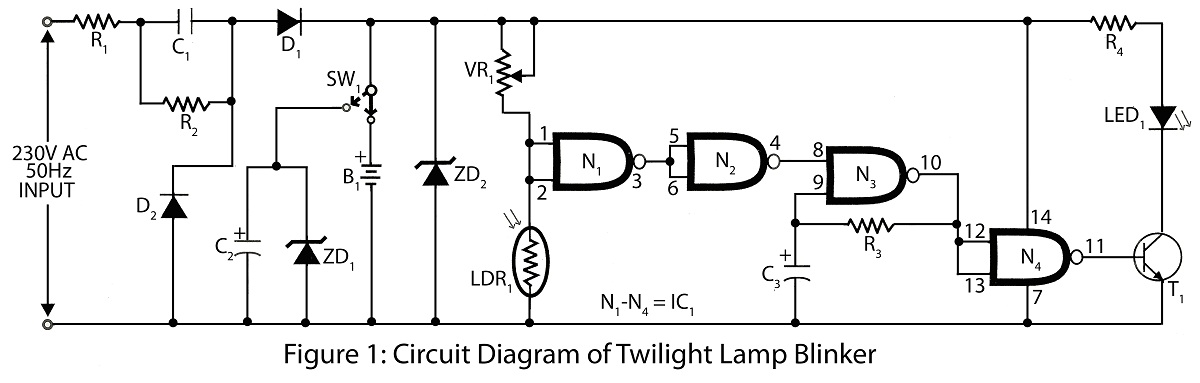
The Twilight Lamp Blinker circuit operates by detecting ambient light levels through the LDR. As the light intensity decreases, the resistance of the LDR increases, triggering the IC to activate the lamp. This functionality is particularly useful in applications where automatic lighting is desired, such as in garden lamps or outdoor lighting systems.
The circuit typically consists of the following components:
1. **LDR (Light Dependent Resistor)**: This component changes its resistance based on the light intensity. In darkness, its resistance is high, while in light, it is low.
2. **Operational Amplifier (Op-Amp) or Comparator IC**: This IC compares the voltage across the LDR with a reference voltage. When the light level falls below a certain threshold, the output of the comparator changes state, allowing current to flow to the lamp.
3. **Transistor**: A transistor is often used as a switch to control the power to the lamp. When the IC output is activated, it turns on the transistor, which in turn powers the lamp.
4. **Resistors and Capacitors**: These components are used to set the reference voltage for the IC and to stabilize the circuit. Resistors limit current flow, while capacitors can help filter noise and stabilize voltage levels.
5. **Power Supply**: The circuit requires a suitable power supply, typically a battery or wall adapter, to provide the necessary voltage and current for the components.
The design can be adjusted for different applications by modifying the values of the resistors and capacitors or by selecting different types of lamps (e.g., LED or incandescent) based on the desired brightness and power consumption. The simplicity and effectiveness of the Twilight Lamp Blinker circuit make it a popular choice for automatic lighting solutions.Twilight Lamp Blinker circuit can be built with LDR and single IC circuit diagram with parts list of twilight lamp blinker various project using LDR and many more. 🔗 External reference
Related Circuits
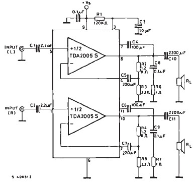
The TDA2005 car audio amplifier circuit is specifically designed for use in devices such as car radios and CD players. This amplifier circuit utilizes the TDA2005 audio integrated circuit (IC), which can deliver a maximum output power of 20...
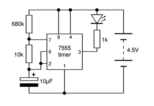
The 7555 timer IC used is a low power version of the standard 555 timer. A super bright red LED is utilized because it provides a bright flash with low current. The 7555 timer IC is a versatile low-power component...
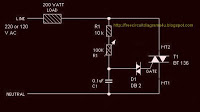
The circuit operates by adjusting the firing angle of the Triac. Resistors R1, R2, and capacitor C2 are involved in this process. The firing angle can be modified by changing the value of any of these components, with R1...
This circuit operates a LED in pulsing mode, i.e. the LED goes from off state, lights up gradually, then dims gradually, etc. This operation mode is obtained by a triangular wave generator formed by two op-amps contained in a...
Here is a circuit diagram for adjusting the brightness of a light bulb. The second battery is utilized to power the circuit. This circuit can be used to modify the brightness of images during close-up photography with a digital...
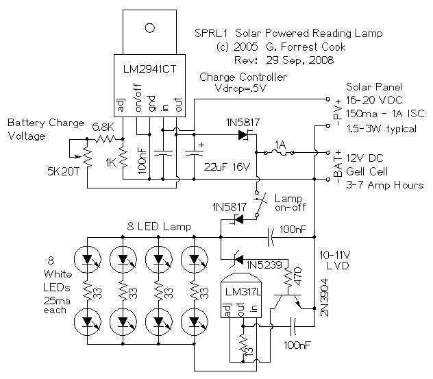
The reading lamp consists of a small solar panel, a standard UPS style lead acid battery, and an LED circuit board. The circuit board contains a low power solar charge controller (regulator), a set of 8 white LEDs, a...
Warning: include(partials/cookie-banner.php): Failed to open stream: Permission denied in /var/www/html/nextgr/view-circuit.php on line 713
Warning: include(): Failed opening 'partials/cookie-banner.php' for inclusion (include_path='.:/usr/share/php') in /var/www/html/nextgr/view-circuit.php on line 713