
Two Homing type Direction-Finding

Adjustment and Calibration: After constructing the circuit, two adjustments are necessary. First, set R4 ("Pitch Adjust") to the midpoint of its rotation. Tune in a signal and set the volume control to a very low setting, lower than usual operational levels. Turn R1 fully clockwise, positioning the potentiometer wiper closest to C1. Rotating the antenna should produce a varying tone based on its orientation. Next, reduce R1 until the unit no longer responds to the antenna's orientation, then increase it slightly until the unit begins to respond again. This adjustment ensures R1 is set above the "ragged edge" at the lowest volume level expected during use. Following this, it is advisable to verify that the unit maintains proper response at the highest anticipated volume level. Adjusting R4 will determine the "pitch" of the audible tone, which will vary during regular operation.
The circuit design and operation illustrate a sophisticated approach to antenna selection and signal processing, utilizing phase detection and modulation principles to enhance signal clarity and directional accuracy. The integration of the NE565 PLL IC as a dual-purpose component exemplifies efficient circuit design, allowing for both signal switching and phase detection to achieve the desired audio output. This configuration is particularly useful in applications requiring precise antenna orientation and signal reception, such as in navigation or communication systems.The antenna is simply a pair of vertical dipoles. The diodes in each dipole allows the circuit to select which antenna is active at any given time. When a positive voltage is sent up the coax feedline, diode D1 will conduct and D2 will block, making the left antenna active and disabling the right antenna. A negative voltage will cause D2 to conduc t and D1 to block, reversing the situation - hence the need for the diodes to be installed "backwards" with respect to each other. Either version of the homing unit will switch back and forth between the two antennas at an audio rate.
If the antenna plane is oriented broadside to the incoming signal, there will be little change as the switching is done and the tone will disappear. However, if the antenna plane is oriented in any other way, the two antennas will be at different distances from the source: This will cause a change in phase of the received signal at each switch, or, in other words, phase modulation and a resulting tone.
Since phase changes also cause a momentary frequency shift, these switches will appear in the audio of an FM receiver as positive and negative pulses (e. g. the tone. ) If one antenna is closer to the signal source than the other (even if this means an inch or two - even though the signal you are receiving may be miles away) this will cause a tone to appear in the aural unit, allowing the unit to determine which antenna is closer to the source.
The only active device in the aural circuit is an NE565 phase-locked loop (PLL) IC. The circuit does not use it as a PLL, but rather uses its two components: an oscillator and a phase detector. The oscillator is used to send the switching signal to the antennas through R1 and its associated 10-uF capacitor.
The phase comparator portion of the IC is used to measure the amplitude of the switching pulses coming back in the receiver`s audio and also see whether they are in-phase or out-of-phase with the switching squarewave the oscillator (VCO) is putting out. Strong pulses one direction mean that you are far off from the desired broadside bearing in one direction, say left.
As you approach the broadside position, the pulses get weaker, and just disappear as you pass through the "dead-on" position. If you continue rotating, the pulses reappear, but now with their phase reversed compared to the oscillator.
The reappearance of pulses causes the tone to reappear. The phase reversal causes the comparator voltage to be on the other side of center than before, so the frequency of the VCO is also on the other side of it`s center point (for example, lower in pitch). The phase comparator is connected to the VCO internally in the IC, so the phase comparator output (which is following the antenna position) always controls the pitch of the tone heard.
Adjustment and Calibration: Once the circuit is constructed, there are two simple adjustments to be made. First, set R4 ("Pitch Adjust") to the middle of its rotation. Tune in a signal and set the volume control at a very low SETTING (lower than that which you are likely to ever use - you may need to put your ear up to the speaker to hear it well) and turn R1 "up" all of the way (so the wiper of the potentiometer is closest to C1.
) Rotating the antenna back and forth, you should hear the tone go up and down, depending on the antenna`s orientation. Now, turn R1 down and find the point at which the unit no longer responds to the orientation of the antenna - and then turn it back up so the unit just starts to respond: In other words, you are setting R1 above the "ragged edge" at the lowest volume setting that you are likely to use.
Once this is done, you might want to verify that the unit still responds properly at the highest volume control setting that you are likely to use. Adjusting R4: The purpose of R4 is to set the "pitch" of the tone you are hearing. In normal operation, the pitch of the tone will vary depending on 🔗 External reference
Related Circuits
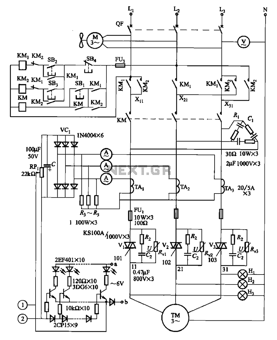
The circuit illustrated in Figure 3-178 is designed for controlling the speed and torque of a motor used in a continuous casting machine. It consists of the main circuit, a trigger circuit, and both manual and automatic control signal...
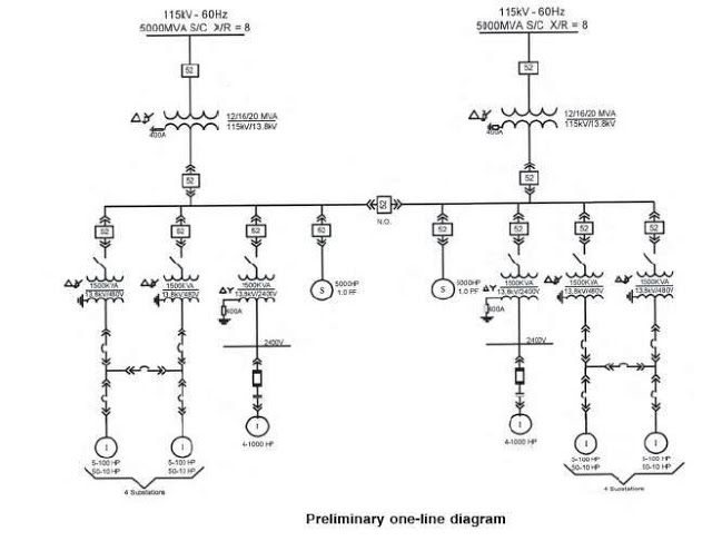
The single line diagram is a circuit diagram where a "one-line" representation illustrates the three phases of a three-phase power system. In addition to displaying the ratings and sizes of electrical equipment and circuit conductors, a well-drawn one-line diagram...
This circuit diagram illustrates a setup for two flashing LEDs designed for various applications, including model construction and recreational uses. It features adjustable flashing speeds controlled by two potentiometers. The circuit comprises a combination of active and passive components....
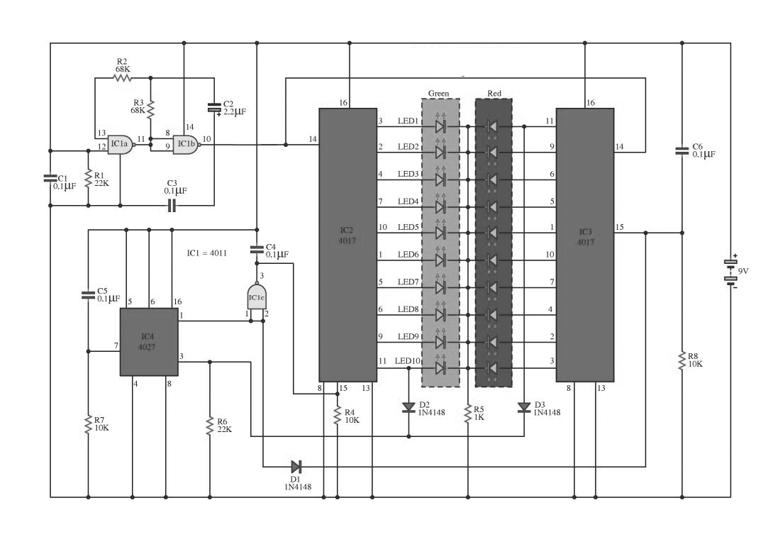
This circuit operates on alternating two colors using a 2-color LED with a built-in 3-pin configuration. It alternates the glow of each LED until the base, switching between two colors. The circuit comprises a NAND gate IC, two 10-counter...
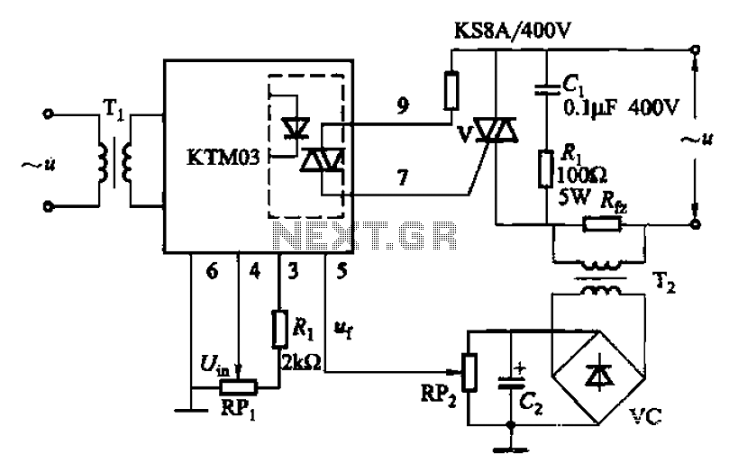
An adjustment potentiometer (RP) is utilized to set the voltage across the load resistor (Rfz) to a predetermined value. The real-time closed-loop control is achieved through the potentiometer (RPz). Open-loop control is functional as long as the feedback voltage...
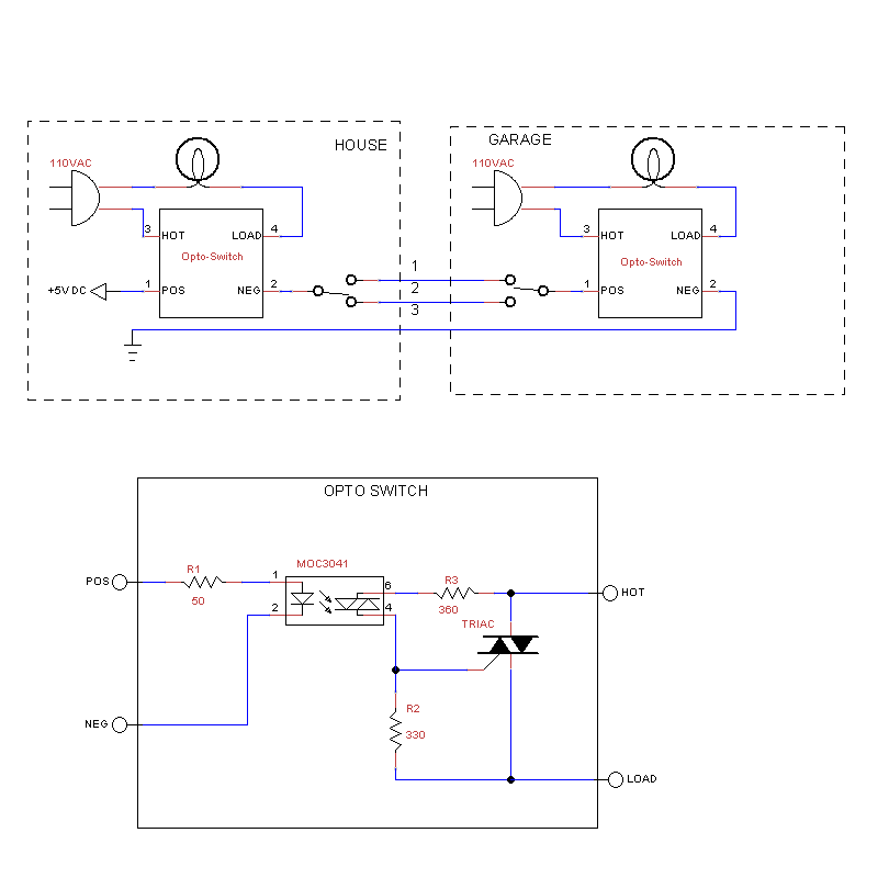
The rewiring of an entire house is underway following a significant malfunction of two antique knob and tube circuits. A challenge has arisen with the outdoor lighting setup, specifically concerning a detached garage that features a porch light above...