
Two Op-Amps 60 Hz Notch Filter

A notch filter, also known as a band-stop filter or band-reject filter, is an essential component in various electronic applications, particularly in audio processing, telecommunications, and signal processing. The primary function of a notch filter is to attenuate a narrow band of frequencies while allowing other frequencies to pass through with minimal loss.
The design of a notch filter can be implemented using passive components like resistors, capacitors, and inductors, or via active components such as operational amplifiers. In a simple passive notch filter configuration, a parallel LC circuit is typically used, where the inductor (L) and capacitor (C) are tuned to resonate at the desired notch frequency.
The transfer function of a notch filter can be expressed mathematically, indicating the filter's frequency response. The notch frequency (f0) is the frequency at which the filter provides maximum attenuation, and the quality factor (Q) determines the bandwidth of the notch. A higher Q value results in a narrower notch, effectively targeting a specific frequency with greater precision.
In practical applications, notch filters are employed to eliminate unwanted interference or noise, such as hum from power lines in audio systems or specific frequency interferences in communication systems. The implementation of a notch filter enhances signal clarity and integrity, ensuring that the desired signals are not adversely affected by unwanted frequency components.
Overall, the notch filter is a vital tool in the field of electronics, providing an effective means of frequency management in various signal processing applications.Notch filter is a filter that remove a certain B. Ideally a notch filter will remove only single point of frequency component, but practically it will remove.. 🔗 External reference
Related Circuits
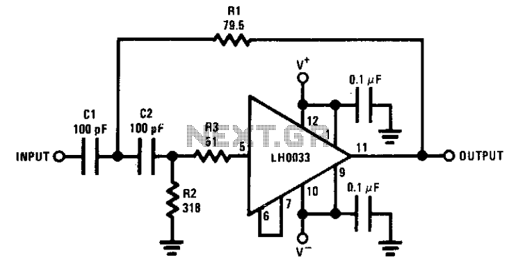
The circuit features a cutoff frequency of 10 MHz. Resistor R3 is utilized to prevent the input capacitance of the amplifier from affecting the filter response at the desired frequency. An equivalent low-pass filter can also be derived through...
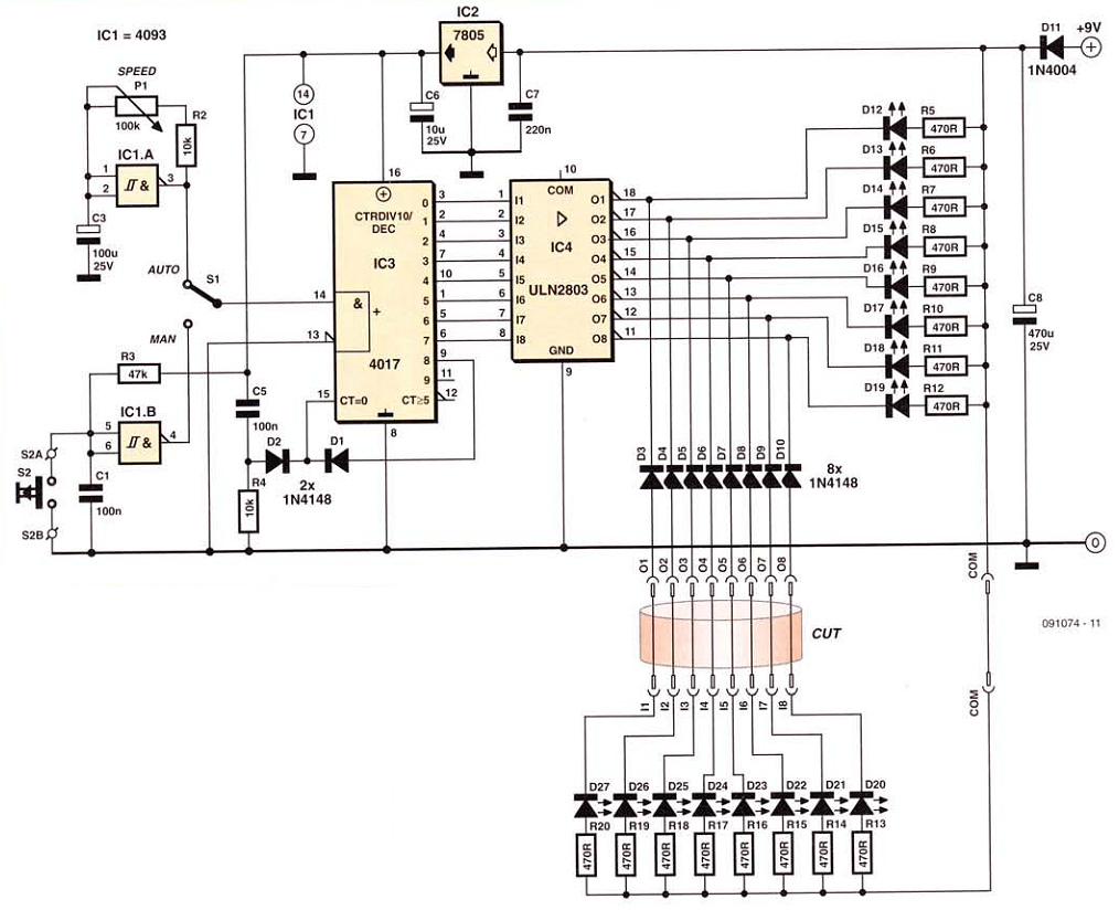
This network wiring tester consists of two components: a transmitter unit, which is powered and installed at the network's starting point, and a passive receiver unit that can be moved from socket to socket. Both units contain eight LEDs,...
The simplest form of motor controllers, apart from a basic on/off switch, is the contactor controller. This contactor controller is recommended for use in electric scooter projects. It is based on three 12V relays, two 12V batteries, two switches,...
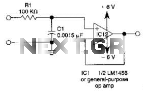
This simple filter utilizes an RC section as the filter element, incorporating a voltage follower to manage other frequencies. The -3 dB point is calculated as 1/(6.28 * RXCV), resulting in a response that drops 6 dB per octave...
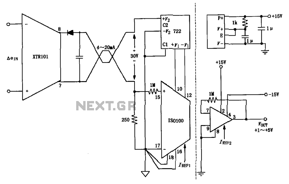
The circuit combines the XTR101 with the ISO100 isolation amplifier to transform a 4-20 mA current signal into a voltage output ranging from +1V to +5V while providing power supply isolation. It features excellent anti-jamming capabilities, making it suitable...
The decimal value of the eight input lines is displayed on three seven-segment displays. Although chips exist to perform this function for single displays, none include the capability of displaying numbers greater than 9. No EPROM is necessary in...