
TWO TRANSISTOR RS232 TO DREAMCAST CONVERTER

The described circuit serves the purpose of interfacing a Sega Dreamcast console with a personal computer (PC) without the need for complex integrated circuits such as the MAXxxx series. Instead, it utilizes a minimal number of discrete components, making it an accessible and straightforward solution for users looking to establish this connection.
The circuit mimics the design of the daVinci cradle schematic, which is known for its efficiency and simplicity. The core components typically involved in such a setup may include resistors, capacitors, diodes, and possibly transistors, depending on the specific requirements for signal conditioning and voltage level shifting between the Dreamcast and the PC.
Signal lines from the Dreamcast would connect to the appropriate input pins on the PC, ensuring that the data transmission adheres to the necessary voltage levels and timing specifications. It is crucial to implement proper pull-up or pull-down resistors as required to maintain signal integrity and prevent floating inputs.
In addition, the circuit may incorporate decoupling capacitors to filter out any noise from the power supply, ensuring stable operation during data transmission. If any analog signals are involved, additional components such as operational amplifiers might be included to buffer or amplify these signals for better compatibility with the PC's input.
This simple yet effective design allows for the seamless transfer of data between the two devices, facilitating various applications such as game emulation or data transfer for development purposes. The absence of complex ICs not only reduces the overall cost of the project but also simplifies the assembly process, making it suitable for hobbyists and engineers alike.A simple circuit to connect the Dreamcast console to PC. No MAXxxx IC required. Only a few discrete components. This circuit is a direct replica of the daVinci cradle schematic: 🔗 External reference
Related Circuits
This is a 28VDC to 5VDC switching converter circuit. As a switch-mode voltage regulator, this circuit provides higher efficiency than linear regulator types. The 28VDC to 5VDC switching converter circuit operates by converting a higher voltage direct current (DC) input...

These circuits are useful for video applications up to 10 MHz. The 3.3-pF capacitors serve as compensation capacitors. The capacitors connected to pins 7 and 4 act as bypass capacitors to prevent self-oscillations. Figure 76-18(a) illustrates a non-inverting configuration,...
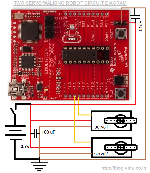
Two small servo motors were purchased last month, leading to the idea of creating a four-legged walker using these two servos. A friend suggested this project and shared a YouTube video demonstrating a similar concept. The design was developed...
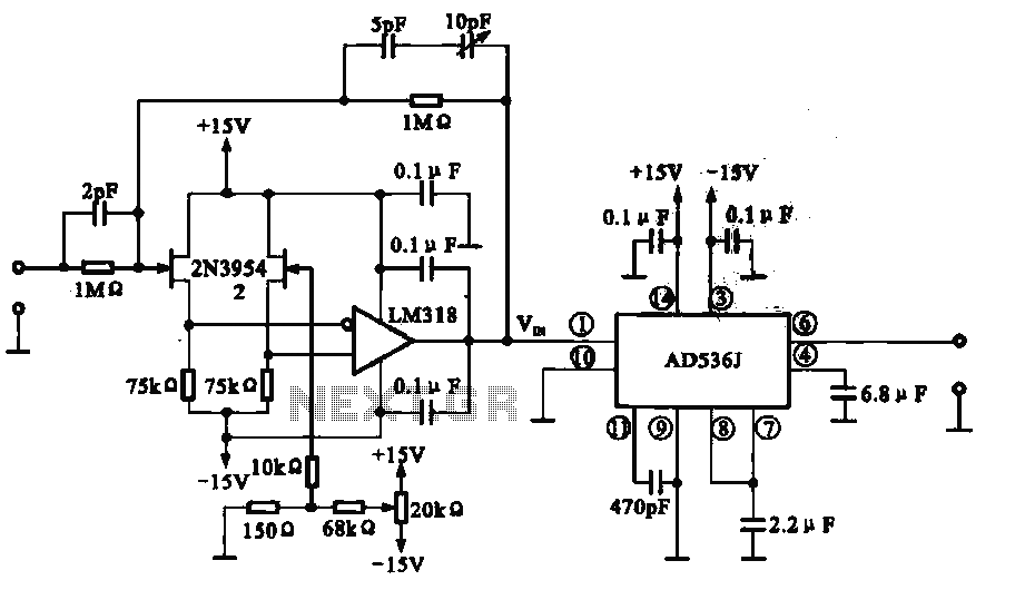
An AC to DC circuit converts sinusoidal alternating current into direct current. If the input signal is not sinusoidal, such as a triangular wave, the distortion is significant. The relationship between the average value and the RMS value is...
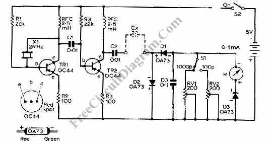
This capacitance meter circuit is similar to previous meter circuits, but it utilizes transistors instead of logic gates. A schematic diagram is provided. The capacitance meter circuit operates by measuring the capacitance of a capacitor through a time-based method. The...
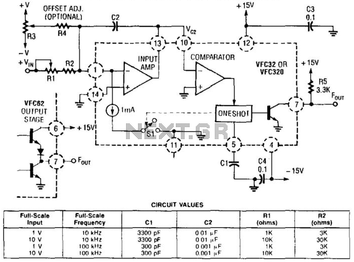
This voltage-to-frequency converter utilizes a Burr-Brown VFC 32 integrated circuit (IC) and requires minimal components. The circuit values are illustrated in the accompanying figure. This charge-balanced voltage-to-frequency (V/F) converter employs either a VFC32 or a VFC320 IC. The positive...