
two servo walking robot using TI launchpad
The project involves the implementation of a two-servo walker utilizing the MSP430G2231 microcontroller, which is part of the Texas Instruments MSP430 series, known for its low power consumption and versatility in embedded systems. The design leverages a circular buffer to manage servo positions, which is particularly useful in scenarios where the hardware resources are limited. This approach allows for the control of multiple servos by using software pulse-width modulation (PWM), which, while not perfect, is sufficient for driving servo motors effectively.
The assembly code is structured to initialize the servos and manage their movement. The use of assembler for coding is beneficial for gaining a deeper understanding of the microcontroller's operation and optimizing performance. The inclusion of specific memory addresses and definitions, such as TOTAL_SERVO and SERVO_BUFFER, indicates careful planning for resource allocation in the limited RAM of the MSP430G2231.
The mechanical design of the walker is crucial for achieving the desired locomotion. By adjusting the angles at which the servos are mounted, the design facilitates the necessary vertical motion to allow for effective walking. This inclination enables the legs to alternate lifting and pushing, mimicking natural movement patterns observed in animals. The simplicity of the circuit, with direct connections to the microcontroller's GPIO pins and a straightforward power supply setup, enhances the overall reliability and ease of assembly of the project.
In summary, this project exemplifies the integration of mechanical design and embedded programming to create a functional robotic walker. The choice of components, programming techniques, and design considerations all contribute to the successful operation of the two-servo walker, showcasing the capabilities of the MSP430 microcontroller in robotics applications.Hi, I bought two small servo motors last month. I was thinking what I can do with this two servo, since it is only two in number. Then I asked this to my friend Achu Wilson and he suggested me to try a four legged two servo walker and he shown a youtube video in which some one demonstrating it. Then I also got interested to make some thing similar to that. Then I started designing my walker using two servo and msp430 launchpad and at last it turned out even better than I thought it would. (See the video above). The servo controlling techinque used here is a little bit different compared to the usual hardware PWM, I used a circular buffer to save each servo position and o/p pin details.
Only a timer compare interrupt is used for this. This is a common technique used for controlling more servo using a cheap microcontroller with limited hardware Timer-pwm modules. Using this software pwm(not a perfect pwm, but still it will work in the servo motors) techinque, I can control more servo motors like 4, 5, 6 etc etc depending on the number of I/O pins.
Coding for this msp430 launchpad is done in asm just because I also want to refresh the msp430 assembly language programming. I used naken430asm assembler in linux for the purpose. Just imagine a lizard or a crocodile creeping. We could see that it will raise one leg and will apply force with another leg and this is done alternatingly with all the four legs which results in the motion.
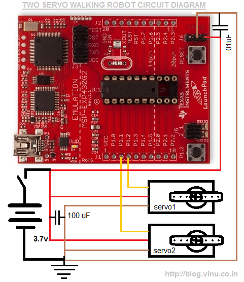
It means, we need a small up and down motion also. But if we are designing it as in above figure(top wrong), we cannot make small vertical movement, ie always the four legs will have a contact with the ground. This will prevent it`s movement in the horizontal plane. To overcome this problem, I need to design it as shown in the second figure(marked as right). There I made a small inclination between the two planes on which each servo is attached. Circuit is simple, just need to connect the servo inputs to the P1. 1 and P1. 2 pins of ti launchpad with MSP430G2231 microcontroller and then as usual, need to connect the power supply to the launchpad board and the servo.
I used 3. 7V battery to power it(an old nokia BL-5C battery). Two servo two directional walking robot with ti launchpad msp430g2231 naken430asm development platform: linux servo connections: P1. 1 & P1. 2 ;. include "msp430g2x31. inc" #define TOTAL_SERVO 2 #define TOP_OF_RAM 0x27f #define CALIBC1_1MHZ 0x10ff #define CALDCO_1MHZ 0x10fe #define SERVO_INDEX TOP_OF_RAM #define SERVO_BUFFER TOP_OF_RAM-(TOTAL_SERVO+1)*4)-3 #define TOP_OF_STACK SERVO_BUFFER - 2 #define SERVO_START_ANGLE SERVO_BUFFER #define SERVO_STAR: ;startup code whichall #walk_forward dec r14lay mov.
w #2000, &(SER 🔗 External reference
Related Circuits
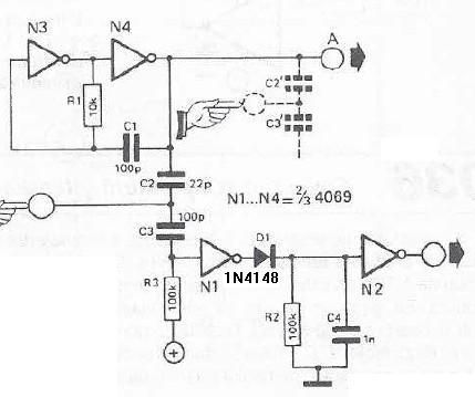
This touch sensor switch is designed using inverters (N1, N2) and several common electronic components. In the standby state, a signal is produced by oscillator N3/N4 at the inputs of N1. When the touch sensor is activated, the hand...
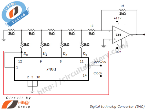
A Digital to Analog Converter (DAC) is utilized to produce an analog voltage that corresponds to input digital data. Binary data can be transformed into its analog equivalent using an R-2R ladder network combined with a summing amplifier, which...

The circuit illustrated briefly flashes an LED to attract attention and remains illuminated as long as power is supplied. The circuit utilizes the well-known 555 timer integrated circuit (IC) configured as a standard astable multivibrator with resistors RA, RB,...

The operation and circuit diagram of a low-cost amplifier utilizing BC107 and BC148 transistors are explained in detail. The low-cost amplifier circuit employs two types of transistors, BC107 and BC148, which are commonly used for their favorable characteristics in audio...
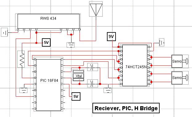
RF technology is an exciting field to incorporate into electronic designs. However, for beginners, constructing reliable RF transmitters and receivers can be challenging. RF (Radio Frequency) technology plays a crucial role in modern communication systems, enabling wireless data transmission over...
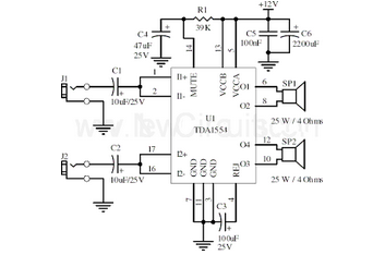
This document presents a 22-watt stereo audio power amplifier circuit diagram based on the TDA1554 integrated circuit from NXP Semiconductors (formerly Philips Semiconductors). The 22-watt stereo audio power amplifier circuit utilizing the TDA1554 IC is designed to deliver high-quality audio...
Warning: include(partials/cookie-banner.php): Failed to open stream: Permission denied in /var/www/html/nextgr/view-circuit.php on line 713
Warning: include(): Failed opening 'partials/cookie-banner.php' for inclusion (include_path='.:/usr/share/php') in /var/www/html/nextgr/view-circuit.php on line 713