
Ultrasonic Bat reciever
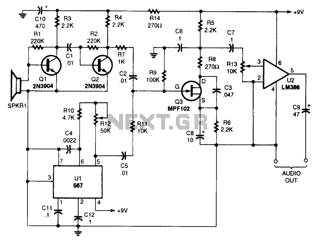
The ultrasonic receiver circuit is designed to capture high-frequency sound waves beyond the human hearing range, typically above 20 kHz. The piezo tweeter acts as a sensitive microphone, converting ultrasonic sound waves into electrical signals. The first stage of amplification, represented by transistors Q1 and Q2, boosts the weak signals received from the piezo element.
The 567 phase-locked loop (PLL) IC operates as a local oscillator, generating a stable frequency to facilitate the demodulation process. This IC is crucial for maintaining the frequency stability necessary for accurate signal processing. The mixer stage, implemented with transistor Q3, combines the incoming ultrasonic signals with the local oscillator output, effectively shifting the frequency of the ultrasonic signals down into the audible range. This heterodyning process allows the originally inaudible sounds to be transformed into a frequency range that can be processed by standard audio equipment.
The final amplification stage, represented by U2, is responsible for driving headphones. This stage ensures that the output signal is strong enough for clear audio reproduction, allowing the listener to hear the converted ultrasonic sounds. The entire circuit is designed to be compact and efficient, making it suitable for various applications, including wildlife observation, mechanical diagnostics, and other scenarios where ultrasonic sound detection is beneficial.You won't be disappointed with the performance of this sensitive ultrasonic receiver. It can let you listen to bugs, bats, engines, and virtually any other source of ultrasonic sounds. The circuit uses a piezo tweeter as an ultrasonic microphone, amplifier stages Ql, Q2, and an LO using a 567 IC. Q3 is a mixer that heterodynes the ultrasonic sounds down to the audible range. U2 is an amplifier that will drive a pair of headphones. U2 is an amplifier that will drive a pair of headphones. 🔗 External reference
Related Circuits
This is a low-cost universal battery charger circuit. This circuit is designed to charge NiCd and NiMH batteries and is ideal for use in vehicles. The circuit converts mains voltage. The low-cost universal battery charger circuit is engineered to efficiently...
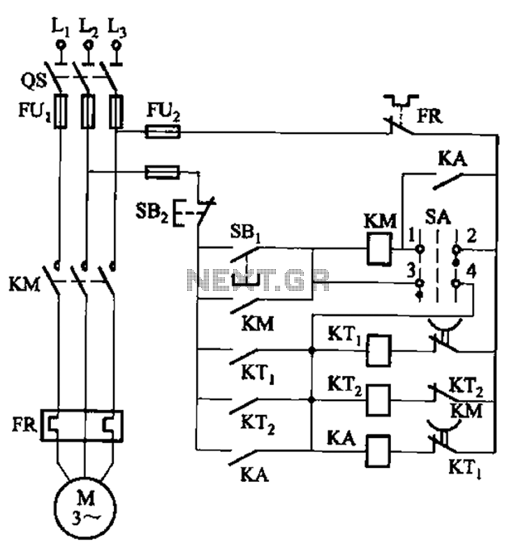
The circuit illustrated in Figure 3-78 utilizes two relays for automatic control, featuring a more complex line structure. This configuration allows for intermittent motor operation. Additionally, it can operate continuously when switch SA is positioned to the right. The circuit...
As the circuit operates, the three sets of diodes with their isolation capacitors build up an increasing voltage on capacitor C1. The voltage at point B will also increase and be about twelve volts less than the voltage on...
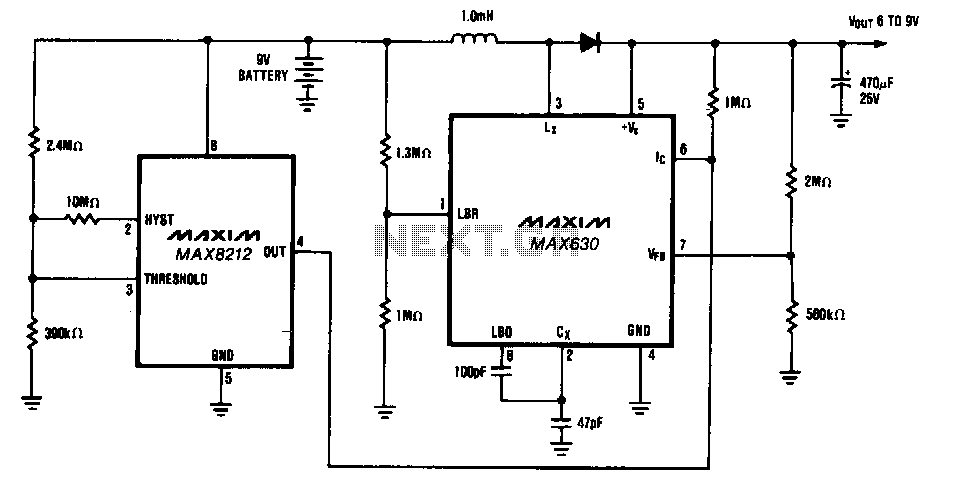
The circuit provides a minimum output of 7 V until the 9-V battery voltage drops below 2 V. When the battery voltage is above 7 V, the MAX630's IC pin is low, placing it in shutdown mode, which consumes...
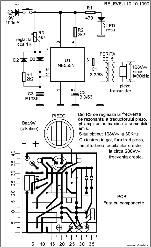
This ultrasonic dog repeller circuit is designed to deter aggressive dogs. It is constructed using the well-known 555 timer circuit, a buzzer, and a small ferrite transformer. The ultrasonic dog repeller circuit operates by emitting high-frequency sound waves that are...
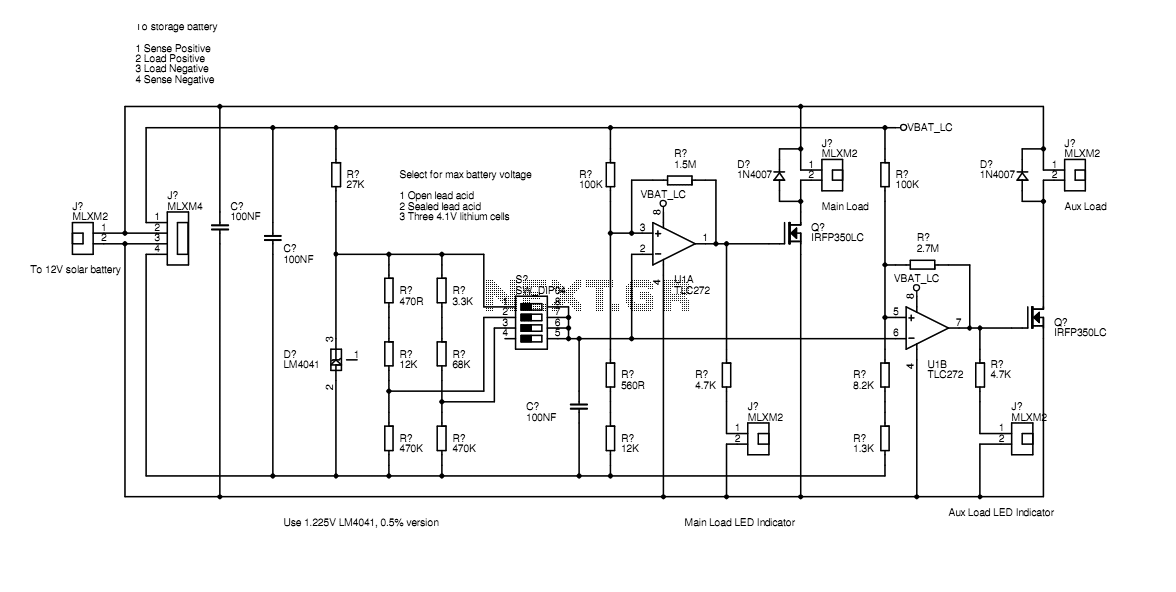
In the actual device the transistors are bolted to the aluminium case. The schematic diagram shown here represents how the circuit would be built if all components were on-board. Separate paths for load current and voltage sensing allow the...